No products in the cart.
Need help? Call us:
+1 (833) 763-7837
Menu
Categories
- Accessories
- Air Purification Accessories
- Antennas
- Attenuators
- Barcode Scanners
- Batteries and Chargers
- Bottles and Dispensers
- Cables - Misc
- Carrying Straps, Lanyards and Harnesses
- Carts
- Case and Cart Accessories
- Cases
- Cathodic Protection Accessories
- Coaxial
- Crimper Accessories
- Datacom Accessories
- Dry Block Bath Inserts
- EMI Accessories
- Enclosure Accessories
- FIber Optic Accessories
- Fiber Optic Cables
- Gas Detection Accessories
- General Accessories
- GPIB Adapters
- Heating Elements
- Hipot Accessories
- Hoses - Miscellaneous
- HVAC Accessories
- Induction Heater Accessories
- Input Cards
- Jacks /Adapters /Plugs /Clips /Terminators/Coaxial
- Jobsite Storage and Cabinets
- Knockout Accessories
- Lab Accessories
- LCR Test Fixtures
- LED and LCD Displays
- Manuals
- Material Handling Accessories
- Microphones
- Microscope Accessories
- Motors
- Options
- Pinhole/Holiday Detector Accessories
- Plumbing Accessories
- Precision Measuring Instrument Accessories
- Pressure Calibrator Modules
- Printers and Printing Supplies
- Probes
- Rack Mounts and Stands
- Repair Parts and Fuses
- Scale Accessories
- Shunts
- Software
- Soldering Accessories
- Spectrum Analyzer Accessories
- Static Control Accessories
- Switch and Semiconductor Modules/Access
- Test Fixtures
- Test Leads and Instrument Accessory Kits
- Thermal Imager Accessories
- Training and Education
- Underground Utility Location Accessories
- Vibration Accessories
- Video Accessories
- Voltage Transformer
- Warranty and Calibration
- Amplifiers / Preamps / Preamplifiers
- Audio Equipment
- Automotive Test Tools
- Battery Testing
- Blower Door and Duct Testing
- Borescopes / Boroscopes
- Clamp Meters
- Cleanroom
- Color and Appearance
- Conduit Benders
- Current Sensors
- Datacom and Networking Products
- Dataloggers Data Acquisition
- Decade Boxes
- Distance Meter
- Electrical Parts and Products
- Cable and Wire
- Cable Reels
- Electrical Cord
- Electrical Jumpers and Pigtails
- Electrical Parts
- Electrical Plugs and Connectors
- Line Splitters
- Lockout / Tagout
- Outlet Boxes
- Pulling Products
- Pushbutton Pendant Stations
- Receptacle Testers
- Temporary Power Distribution
- Terminal Blocks and Strips
- Terminals and Crimps
- Wall Plates
- Wire Management
- Wire Ties
- Work Lighting and String Lighting
- Enclosures and Boxes
- Environmental Testers / Physical Property
- Anemometer / Air Flow
- Barometers and Altimeters
- Chlorine Tester
- Dissolved Oxygen Meter / Fluoride
- EMF / ELF Meter
- Heat Index Monitors
- Humidity Meters
- Hygrometers
- Moisture Meters
- Nuclear Radiation Monitors
- PH / ORP Meters
- Psychrometer
- Refractometers / BRIX
- Scales / Weight
- Sound Level Meters
- Stopwatches / Timers / Clocks
- Water Quality Accessories
- Water Quality Meters
- Weather Measurement
- Wind Tunnels
- Flow Measurement
- Force / Torque / Hardness Meters
- Gas Detection
- Ground Testers
- Health and Safety
- HVAC Equipment and Instruments
- Automotive RRR Machines
- Brazing
- Combustion Analyzers
- Hose Adapters, Valves and Parts
- HVAC - Testing - Adjusting - Balancing
- HVAC Equipment - Misc
- HVAC Manifolds and Gauges
- HVAC Vacuum Pumps
- Refrigerant Leak Detectors
- Refrigerant Recovery Machines
- Refrigerant Recovery Tanks
- Smoke Pump Test Kits
- Tubing Tools
- Vacuum Gauges
- Hydraulic Cylinders
- Indoor Air Quality
- LCR Meters / Impedance Measurement Products
- Leakage Detectors
- Life Sciences Equipment
- Autoclaves and Sterilization
- Bunsen Burners
- Centrifuges
- Cold Storage
- Colony Counters
- Dry Block Heaters and Cooling Blocks
- Environmental Test Chambers
- Flame Photometers
- Flocculators
- Fluidized Bed Baths
- Gel Imaging Electrophoresis
- Glassware Washers-Dryers
- Heating Mantles / Electromantles
- Homogenizers
- Incubators
- Kjeldahl Apparatus
- Lab Apparatus - Misc
- Laboratory Ovens
- Laboratory Pumps
- Laboratory Water Purification Systems
- Magnetic Bead Based Purification
- Melting Point Apparatus
- Mixers Rotators and Stirrers
- Pipettes
- Reaction Station
- Recirculating Chillers / Coolers
- Refrigerated Heating Circulators
- Rotary Evaporators
- Shakers and Rockers
- Slide Warmers
- Spectrophotometer
- Thermal Cycler / PCR
- Titrators
- Water Baths and Liquid Baths
- Logic Analyzers
- Materials Testing
- Megohmmeter / Insulation Resistance Testers
- Micro-Ohmmeter / Milliohmmeter
- Microscopes
- Multimeters
- Network Analyzer
- Oscilloscopes
- Panel Meters
- Personal Protective Equipment
- Phase / Motor / Transformer Testing
- Power Measurement
- Power Supplies
- Process / Calibration
- Programmers / IC and RAM Testers
- Protocol Analyzers
- Prototyping
- Radiometric
- Reliability / Preventative Maint / Rotational
- RF, Microwave, EMI
- Safety Testing / Surge Testing
- Signal Generators / Counters
- Signal Level Meters - CATV / CCTV / Satellite
- Solar Analyzers
- Soldering Equipment
- BGA Rework Station
- Chemicals
- Cleaning Pins and Drills
- Depaneling Systems
- Desoldering Equipment/Rework Stations
- Desoldering Irons
- Dispensing Equipment
- Flux
- Flux Remover
- Fume Extraction
- Hot Air Guns
- Hot Air Pencils
- Lead Forming Equipment
- Nitrogen Generation
- Nozzles
- PCB Supports and Holders
- Pre-Heater
- Solder
- Solder Wick
- Soldering Equipment
- Soldering Irons
- Soldering Pots
- Soldering Robots
- Soldering Stands
- Soldering Stations
- Soldering Tip Cleaners
- Soldering Tip Thermometers
- Soldering Tweezers
- Sponges and Brass Wool
- Thermal Wire Strippers
- Tips
- Vacuum Pick-Up Tools
- Sporting / Hunting / Law Enforcement Optics
- Static Control
- Surveying / Construction Measurement
- Thermal Imagers
- Thermometers
- Thickness Gauges
- Tools
- Blackeners
- Cable Cutters
- Cable Strippers
- Cable Tie Guns
- Combination Squares
- Conduit Tools
- Crimpers
- Cutters
- Cutting Tools
- Datacom / Fiber Optic Tools
- Drill Bits and Sets
- Drill Rod
- Dry Lubricants
- Electric Screwdrivers
- Feeler Gage
- Fiber Optic Cable Tools and Fiber Scopes
- Flashlights and Headlights
- Ground Flat Stock
- Hex Drivers, Torx Drivers
- Hose Benders
- Hose Clamps
- Hot Melt
- HVAC Service Tools
- Insulated Tools
- Keystock
- Knockout Tools
- Layout Fluid
- Level Measurement
- Maintenance Kits
- Multi-Tools
- Other Hand Tools
- Pliers
- Pneumatic Hand Tool Operators
- Power Tools
- Probes & Scribes
- Punch & Die Sets
- Punchdown Tools
- Remote Hydraulic Pumps
- Screwdrivers
- Shims & Shim Stock
- Sockets & Ratchets
- Spatulas
- Telecom Service Tools
- Telescopic Tools
- Threaded Rod
- Tool Kits
- Tool Wrap
- Tweezers
- Vises
- Wire
- Wire Strippers
- Wrenches & Wrench Sets
- Toys / Cool Stuff
- Transmission Line/Station Testing
- Cable Testing
- Circuit Breaker Testers
- Corona Detection
- Dielectric Oil Testing
- High Current Detectors / Indicators
- High Voltage Detectors / Indicators
- Hot Sticks
- Phasing Sticks
- Primary Injection Test Equipment
- Safety Equipment
- Secondary Injection Test Equipment
- SF6 Gas Leak Detectors
- Transformer Testing/TTR
- Transmission Cable Height Meters
- Video Distribution Equipment
- Video Test Equipment
- Voltage / Continuity and Non-Contact Testers
- Wire Tracers / Circuit Breaker Tracers
- Workbenches


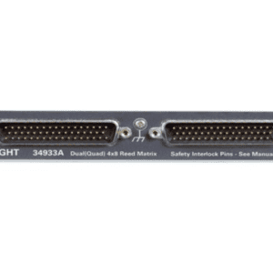
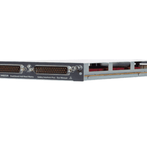

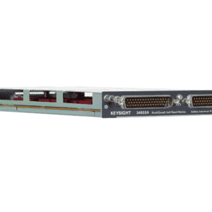
Keysight 34933A – Dual/Quad 4×8 Reed Matrix for 34980A
Brand:
23 people are viewing this product right now
Shipping calculated at checkout.
Estimated delivery:5 days
Dual/Quad 4×8 Reed Matrix Module for 34980A
- Module for 34980A (sold separately)
- Dual 4×8, 8×8, or 4×16 2-wire configurations
- 64 2-wire or 128 1-wire cross-points
- High-speed reed relays
- Connections to the internal DMM
- Expandable via four 2-wire analog buses
- Relay counter
- ±150 V peak, .5 A switch, 1.5 A carry current
SKU:
Keysight 34933A
Tags: Accessories, Switch and Semiconductor Modules/Access
Categories: Switch and Semiconductor Modules/Access
Have any Questions?
Feel free to Get in touch
Guarantee Safe and Secure Payment Checkout
Description
Keysight 34933A – Dual/Quad 4×8 Reed Matrix for 34980A
Using program commands or the front panel of the 34980A, you can configure the 34933A dual/quad 4×8 reed matrix module for differential (2-wire) mode or single-ended (1-wire) mode.
The 34933A module contains 100 ohm in-rush resistors that are used to protect the reed relays from reactive loads. If you have applications where in-rush resistors interfere with measurements, connections are provided on the terminal blocks for you to bypass the in-rush resistors that are located on the columns. However, if you choose to bypass the in-rush resistors, the life of the reed relays that you bypass may be degraded.
Two wire mode
To physically configure the module for 2-wire mode, use the 34933T-001 terminal block, or a compatible standard or custom cable. If using a standard or custom cable, make sure you connect interlock pins 17 and 33 on the Matrix 2 D-sub connector.
In 2-wire mode, the 34933A module contains two matrices, each with 32 2-wire crosspoint non-latching reed relays organized in a 4-row by 8-column configuration. Every row and column are made up of two wires each, a high (H) and a low (L). Each crosspoint relay has a unique channel number representing the row and column that intersect to create the crosspoint. For example, channel 308 represents the crosspoint connection between row 3 and column 08 (all columns consisting of two digits; in this case the digits are 08).
You can connect any combination of inputs and outputs at the same time. However, only Matrix 2 in 2-wire mode of this module connects to the Analog Buses. By closing channels 921 and 922 you can connect rows 5 and 6 respectively to the internal DMM of the 34980A mainframe for voltage and resistance measurements.
In 2-wire mode, you can close no more than 20 channels simultaneously due to power dissipation. However, note that Analog Bus relays count half as much as channel relays in that total. For example, with one Analog Bus relay closed, you can close up to a maximum of 19 channel relays. If you try to close more than the allowed number of channels, you will receive an error message.
One wire mode
To physically configure the module in 1-wire mode, use the 34933T-002 terminal block, or a compatible standard or custom cable. If using a standard or custom cable, make sure you connect interlock pins 17 and 33 on the Matrix 2 D-sub connector.
In 1-wire mode, the 34933A module contains four matrices (1 through 4), each with 32 1-wire crosspoint non-latching reed relays organized in a 4-row by 8-column configuration. Every row and column has one wire each. Each crosspoint relay has a unique channel number representing the matrix, and the single-wire row and column that intersect to make the crosspoint. For example, channel 218 represents Matrix 2, row 1 and column 8.
In 1-wire mode, you can close no more than 40 channels simultaneously due to power dissipation. For example, with one Analog Bus relay closed you can close up to a maximum of 39 channel relays. If you try to close more than the allowed number of channels, you will receive an error message.
You can connect any combination of inputs and outputs at the same time. However, only Matrix 3 and Matrix 4 in 1-wire mode of this module connect to the Analog Buses. By closing channels 921 and 922 you can connect rows 1 and rows 2 respectively to the internal DMM of the 34980A mainframe for voltage and resistance measurements.
You can connect multiple matrix modules externally and/or through the Analog Buses for applications that require large matrices.
When the power is off, matrix relays and Analog Bus relays open.
Terminal blocks (sold separately)
This terminal block with screw-type connections is labeled with the model number and the abbreviated module name. In addition, space is available on the label for you to write the slot number
- 34933T-001 – Terminal block for two-wire mode
- 34933T-002 – Terminal block for one-wire mode
Additional information
For additional information on the 34933A, please see the document linked here beginning on page 27.
34980A matrix modules
The chart below provides an overview of matrix modules for the 34980A.
| Model | Model Description | Max voltage | Switch/carry | Scan ch/sec |
| 34931A | Dual 4×8 armature matrix | ±300V | 1A/2A | 100 |
| 34932A | Dual 4×16 armature matrix | ±300V | 1A/2A | 100 |
| 34933A | Dual/quad 4×8 reed matrix | ±150V | 0.5A/1.5A | 500 |
| 34934A | Quad 4×32 reed matrix | ±100V | 0.5A/1.5A | 500 |
Be the first to review “Keysight 34933A – Dual/Quad 4×8 Reed Matrix for 34980A”
You must be logged in to post a review.
Manuals/Guides
ManualsSpec Sheets
Related products

Sale

Televes 149281 – V Zenit antenna UHF


 Keysight 34933A – Dual/Q...
 $1,823.00
Our team of knowledgeable professionals is here to help you make informed decisions. Whether you need product recommendations, technical support, or guidance on your purchase, we're just a click away.
Contact Us Now:
📧 sales@nestesinstruments.com
📞 +1 (833) 763-7837
Let us assist you in finding the perfect solution!
Contact Us Now:
📧 sales@nestesinstruments.com
📞 +1 (833) 763-7837
Let us assist you in finding the perfect solution!
Reviews
There are no reviews yet.