No products in the cart.

Description
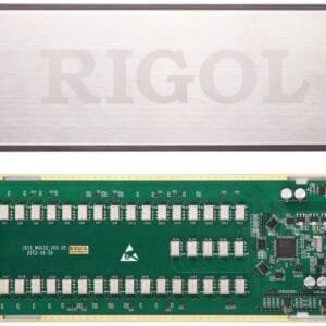
Rigol MC3132 MUX32 Module 32-channel Multiplexer.
32 channel differential Multiplexer module for use with M300 DAQ System Mainframe and MC3065 DMM module. Configurable for 2 or 4 wire measurements. The M3TB32 is the mating terminal block for this module.
MC3132 (32-Channel Multiplexer):
All 32 channels switch both HI and LO inputs, thus providing fully isolated inputs to the DMM module. MC3132 is divided into two banks (called A and B) of 16 two-wire channels each. When making 4-wire resistance measurement, the instrument automatically pairs channels of A bank and B bank. All channels are break-before-make. You can close multiple channels on this module only if you have not configured any channel to be part of the scan list. This module can be connected with MC3065 (DMM Module, if MC3065 is currently inserted).
Measurement Connections Using External Terminal Blocks
M300 provides 6 kinds of terminal blocks to easily connect the signal to be measured to the module. The models of the terminal blocks and corresponding modules are listed in the table below. This section introduces how to use the external block.
| Terminal Block | Module | |
| 1 | M3TB32 | MC3132, MC3232 |
| 2 | M3TB64 | MC3164, MC3264 |
| 3 | M3TB24 | MC3324 |
| 4 | M3TB48 | MC3648 |
| 5 | M3TB16 | MC3416 |
| 6 | M3TB34 | MC3534 |
Note: for the MC3724, the signal can be connected to the SMB connectors on the module directly. No terminal block is needed.
WARNING: Cut off all the power supplies before opening the terminal block or removing the terminal block from the module.
1. Place the terminal block with the front (with the RIGOL caption) facing downward and pull the two latches in the arrow direction in the figure below and press them down. Place the terminal block with the front facing upward and pull the upper cover of the terminal block upward and remove it.

2. Connect the cables for connecting the signal under test according to the labels on the circuit board of the terminal block (for the connecting method, refer to Table 1-1). Pass the binding wires through the two groups of holes as pointed out by the arrows in the figure below to fix the cable connected. Pay attention to the channel or terminal connected to the cable to ensure that the signal connected is correct.

3. Connect the terminal block to the module via interface 1 (the interface definition is in Figure 1-7) on the module and screw down the two screw rods onto the nuts on the module.

4. Close the upper cover of the terminal block.

5. Insert the module with the terminal block into the slot of the mainframe.

Product General Attributes | |
|---|---|
| Product Height | 6.00 IN |
| Product Length | 17.00 IN |
| Product Width | 9.00 IN |
| HTS/Schedule B Number | 9030908961 |
| ECCN Number | EAR99 |
| Country of Origin | China |
| Shipping Height | 6.00 IN |
| Shipping Length | 17.00 IN |
| Shipping Width | 9.00 IN |
You must be logged in to post a review.
| Dimensions | 17 × 9 × 6 in |
|---|
Related products
Sale

Mastercool 52254 – Antenna Type Probe
Original price was: $264.17.$254.01Current price is: $254.01. Add to cart
Sale

Televes 560383 – Kit: Mast Amplifier with BOSS-Tech and “F” Power Supply Unit (Repack Ready)
Original price was: $87.94.$76.94Current price is: $76.94. Add to cart

 Rigol MC3132 MUX32 Module
 $477.00
Our team of knowledgeable professionals is here to help you make informed decisions. Whether you need product recommendations, technical support, or guidance on your purchase, we're just a click away.
Contact Us Now:
📧 sales@nestesinstruments.com
📞 +1 (833) 763-7837
Let us assist you in finding the perfect solution!
Contact Us Now:
📧 sales@nestesinstruments.com
📞 +1 (833) 763-7837
Let us assist you in finding the perfect solution!
Reviews
There are no reviews yet.