No products in the cart.


Description

Digilent MCC 128
- 8 SE/4 DIFF 16-bit voltage inputs
- 100 kS/s max sample rate (320 kS/s aggregate for stacked boards)
- Multiple input ranges (+/-10 V, +/-5 V, +/-2 V, +/-1 V)
- Onboard sample buffers allow high-speed acquisition
16-Bit Voltage Measurement DAQ HAT for Raspberry Pi
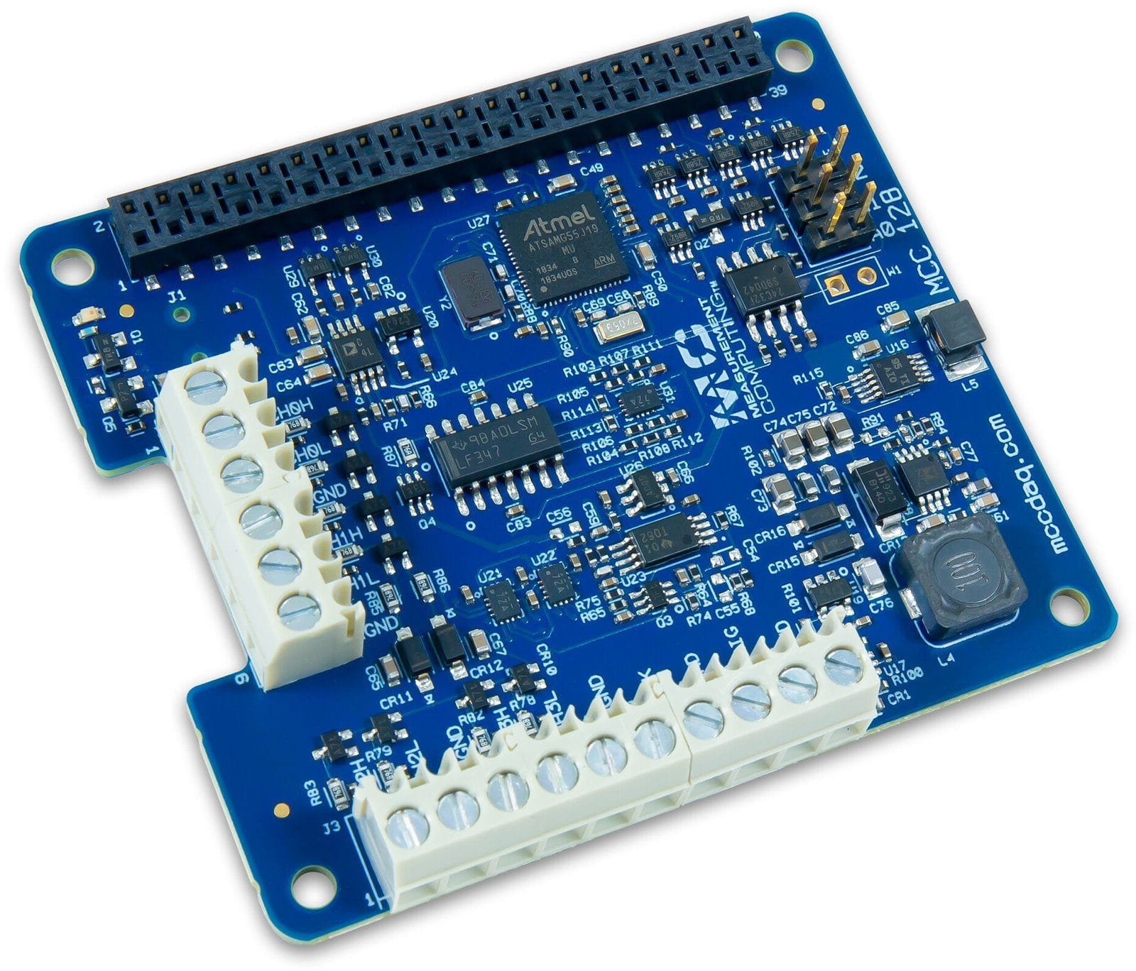
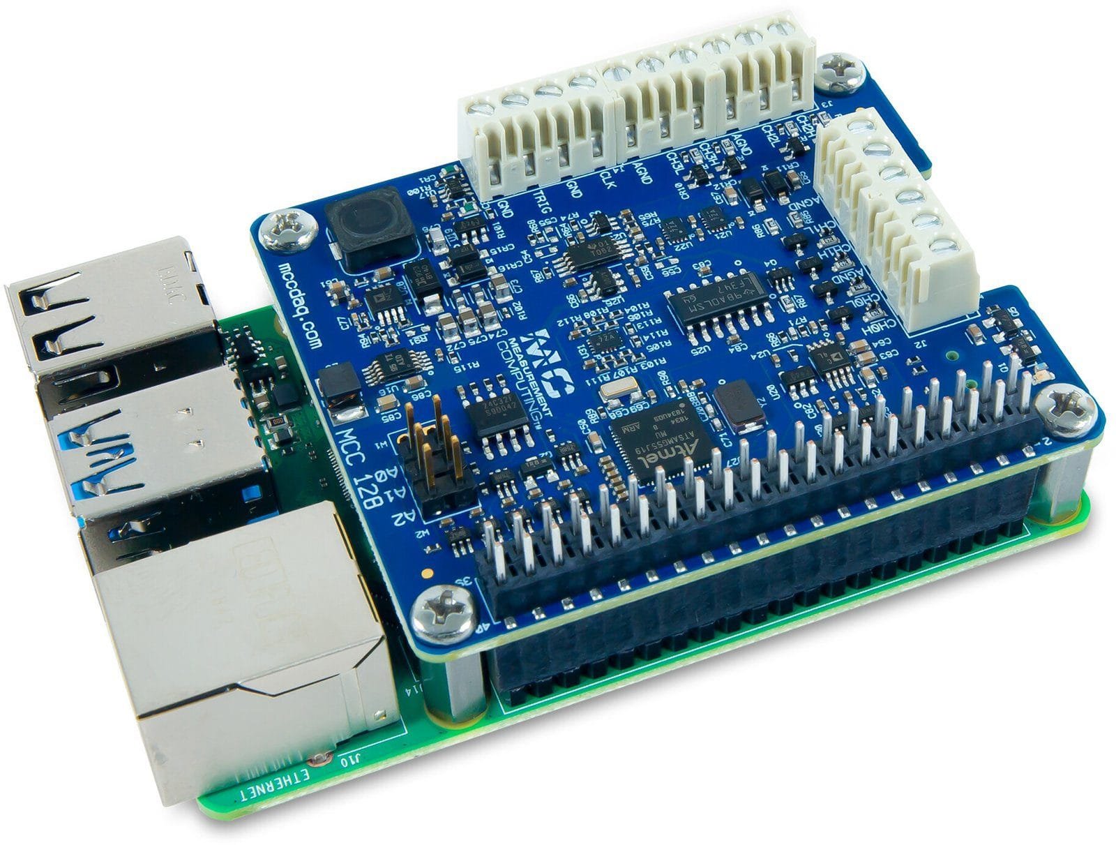
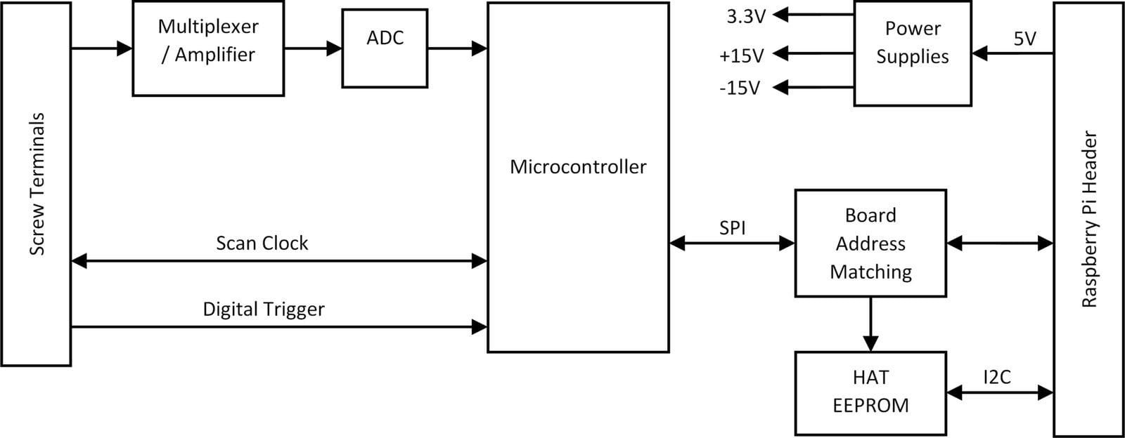
The Measurement Computing MCC 128 is a voltage HAT (Hardware Attached on Top) board designed for use with Raspberry Pi®. It provides eight single-ended (SE) or four differential (DIFF) analog inputs with the following input ranges (+/-10 V, +/-5 V, +/-2 V, +/-1 V). A bidirectional clock I/O pin lets users pace operations with an external clock signal or with the board’s internal scan clock. Use software to set the direction. The external digital trigger input is software-configurable for rising or falling edge, or high or low level. The MCC 128 is powered with 3.3 V provided by the Raspberry Pi through the GPIO header connector.
HAT configuration parameters are stored in an onboard EEPROM that allows the Raspberry Pi to automatically set up the GPIO pins when the HAT is connected. The open-source MCC DAQ HAT Library of commands in C/C++ and Python allows users to develop applications on the Raspberry Pi using Linux. The MCC DAQ HAT Library supports operation with multiple MCC DAQ HATs running concurrently. Console-based and user interface (UI) example programs are available for each API.


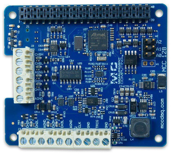
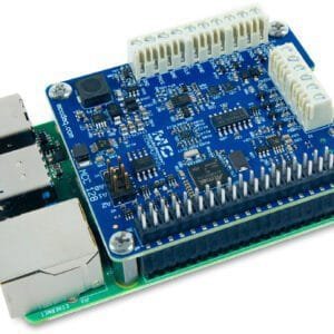
Board components
Screw Terminals
- CH0H/CH0L to CH3H/CH3L (CHx): Analog input terminals.
- Clock (CLK): Bidirectional terminal for scan clock input / output. Set the direction with software. Set for input to clock the scans with an external clock signal, or output to use the internal scan clock.
- Trigger (TRIG): External digital trigger input terminal. The trigger mode is software configurable for edge or level sensitive, rising or falling edge, high or low level.
- AGND (GND): Common ground for the analog input terminals.
- DGND (GND): Common ground for the clock and trigger terminals.
Address Jumpers
- A0 to A2: Used to identify each HAT when multiple boards are connected. The first HAT connected to the Raspberry Pi must be at address 0 (no jumper). Install jumpers on each additional connected board to set the desired address.
Status LED
The LED turns on when the board is connected to a Raspberry Pi with external power applied and flashes when communicating with the board. The LED may be blinked by the user.
Header Connector
The board header is used to connect with the Raspberry Pi.

Functional Details
Scan Clock
The clock input/output (terminal CLK) is used to output the internal scan clock or apply an external scan clock to the device. The clock input signal may be a 3.3V or 5V TTL or CMOS logic signal, and the output will be 3.3V LVCMOS. A scan occurs for each rising edge of the clock, acquiring one sample from each of the selected channels in the scan. For example, when scanning channels 0, 1, and 2 the conversion activity will be:

Trigger
The trigger input (terminal TRIG) is used to hold off the beginning of an analog input scan until the desired condition is met at the trigger input. The trigger input signal may be a 3.3V or 5V TTL or CMOS logic signal. The input condition may be a rising edge, falling edge, high level, or low level.
Firmware Updates
Use the firmware update tool to update the firmware on your MCC 128 board(s). The “0” in the example below is the board address. Repeat the command for each MCC 128 address in your board stack. This example demonstrates how to update the firmware on the MCC 128 that is installed at address 0: mcc128_firmware_update 0 ~/daqhats/tools/MCC_128.fw
Dataloggers / Data Acquisition/Voltage Datalogger Template | |
|---|---|
| # Inputs/Channels | 8 |
| SAMPLE RATE/Intervals | 100 kS/s |
| LCD Screen | No |
| Software Included | Yes |
| Type | DC |
Product General Attributes | |
| Product Height | 0.47 IN |
| Product Length | 2.56 IN |
| Product Width | 2.22 IN |
| Shipping Weight | 1.00 LBS |
| Data Logging | Yes |
| HTS/Schedule B Number | 8471809000 |
| ECCN Number | EAR99 |
| Country of Origin | Hungary |
| Shipping Height | 3.00 IN |
| Shipping Length | 1.00 IN |
| Shipping Width | 3.00 IN |
You must be logged in to post a review.
Manuals/Guides
Spec Sheets
| Dimensions | 2.56 × 2.22 × 0.47 in |
|---|
Related products


Sale
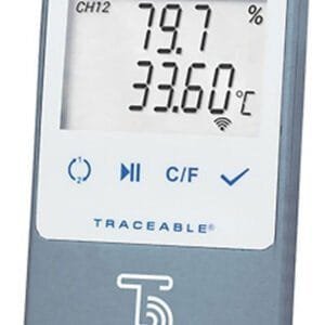
Digi-Sense 18000-29 – Digi-Sense Temperature/Humidity Data Logger with TraceableLIVE Wireless Capability and Calibration; 1 Dongle
Original price was: $387.20.$322.66Current price is: $322.66. Add to cartSale

Digi-Sense 18000-30 – Temperature/Humidity Data Logger with TraceableLIVE® Wireless Capability and Calibration; 1 Probe with cable
Original price was: $410.30.$341.91Current price is: $341.91. Add to cartSale

Digi-Sense 18000-32 – High-Range CO2/Temperature/Humidity Data Logger with TraceableLIVE Wireless Capability and Calibration
Original price was: $840.40.$700.33Current price is: $700.33. Add to cart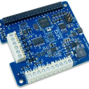 Digilent MCC 128 – 16-Bi...
 $218.90
Our team of knowledgeable professionals is here to help you make informed decisions. Whether you need product recommendations, technical support, or guidance on your purchase, we're just a click away.
Contact Us Now:
📧 sales@nestesinstruments.com
📞 +1 (833) 763-7837
Let us assist you in finding the perfect solution!
Contact Us Now:
📧 sales@nestesinstruments.com
📞 +1 (833) 763-7837
Let us assist you in finding the perfect solution!
Reviews
There are no reviews yet.