No products in the cart.
Sale


Description
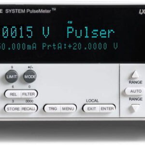
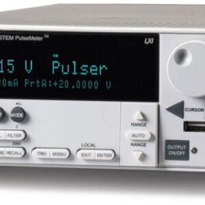
Keithley 2601B-PULSE – Single-channel System SourceMeter, 10usec Pulser/SMU Instrument

- Channels: 1
- Max Current Source/Measure Range: 10 A
- Max Voltage Source/Measure Range: 40 V
- Measurement Resolution (Current / Voltage): 100 fA / 100 nV
The new 2601B-PULSE System SourceMeter 10 µs Pulser/SMU Instrument with PulseMeter™ technology is an industry-leading high current/high speed pulser with measure plus the full functionality of a traditional SMU. This new pulser offers leading 10 A current pulse output at 10 V with a pulse width minimum of 10 µs, perfect for testing vertical cavity surface emitting lasers (VCSEL) used in LIDAR and facial recognition, LEDs for lighting and displays, semiconductor device characterization, surge protection testing, and so much more. The pulser’s built-in dual 1 Mega sample/second (MS/s), 18-bit digitizers make it possible to acquire both pulse current and voltage waveforms simultaneously without the need to use a separate instrument.
The 2601B-PULSE is a powerful solution that significantly boosts productivity in applications ranging from benchtop characterization through highly automated pulsed I-V production test. For automated system applications, the 2601B-PULSE’s Test Script Processor (TSP®) runs complete test programs from inside the instrument for industry-best throughput. In larger, multi-channel applications, the Keithley TSP-Link® technology works together with TSP technology to enable high-speed, pulser/SMU-per-pin parallel testing. Because the 2601B-PULSE offers full isolation that does not require a mainframe, it can be easily reconfigured and re-deployed as your test applications evolve.

External Interlock/Connector box included with 2601B-PULSE
Pulsed Testing for Device Characterization
Testing real device operation and minimizing the heating effects with on-wafer testing just got easier with the 2601B-PULSE SMU. Thermal management is critical during the testing of many devices, especially those at the semiconductor wafer level, such as VCSELs, laser diodes, and LEDs. Pulsed I-V testing minimizes the heating effects of the current in the device, especially if tested at the wafer level when devices have no temperature control circuitry. Testing with DC would either change their characteristics, or at worst, destroy them. Later on, in production, when they have been assembled into modules with temperature controls, the devices can be DC tested and the results compared to those from the pulsed test. Some devices will pass a DC test and fail a pulsed test due to device characteristic changes resulting from temperature shift. The 10 V / 10 A / 10 µs output of the 2601B-PULSE ensures that you get a proper output pulse into your device and an accurate measurement when it is required.
No Tuning Required
When outputting current pulses, cabling and inductance can be a problem. Inductance can have a limiting effect and could even be damaging. Quite often, the inductance can be different from device to device, even when testing laser diodes on a wafer. The effect of inductance on a current source is that inductance resists changes in current. This can cause the current source to increase the output voltage. The result is overshoot and ringing as the pulse settles. This may not be acceptable in your test. Some solutions require tuning to compensate for these behaviors, which can be time consuming. The 2601B-PULSE’s control loop system eliminates the need to tune for load changes up to 3 μH so that your pulse has no overshoot and ringing when outputting pulses from 10 μs up to 500 μs at a current up to 10 amps. This ensures a fast rise time, so your devices are sourced with a current pulse to properly characterize the device or circuit. The images on the next page show the performance of the 2601B-PULSE with PulseMeter technology compared to a competitive modular SMU outputting a 5 A, 50 μs pulse on a device with an impedance of 3 µH.

Pulse output performance of the 2610B-PULSE SMU.
Unmatched Throughput for Automated Test with TSP Technology
For test applications that demand the highest levels of automation and throughput, the 2601B-PULSE’s TSP technology delivers industry-best performance. TSP technology goes far beyond traditional test command sequencers – it fully embeds, then executes, complete test programs from within the SMU instrument itself. This virtually eliminates the time consuming bus communications to and from the PC controller, and thus dramatically improves overall test times.
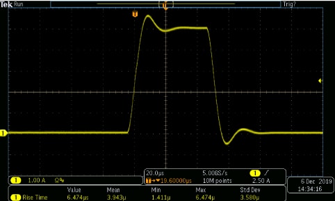
Typical pulse output from a competitive SMU with overshoot and 6.47 μs rise time.

TSP technology executes complete test programs from the non-volatile memory of the 2601B-PULSE.

2601B-PULSE output without overshoot and 1.4 µs rise time.

All channels in the TSP-Link system are synchronized to under 500 ns.
SMU-Per-Pin Parallel Testing with TSP-Link Technology
TSP-Link is a channel expansion bus that enables multiple 2601B-PULSE SMUs to be inter-connected and function as a single, tightly-synchronized, multi-channel system. The 2601B-PULSE’s TSP-Link technology works together with its TSP technology to enable high-speed, SMU-per pin parallel testing. Unlike other high-speed solutions, such as large ATE systems, the 2601B-PULSE achieves parallel test performance without the cost or burden of a mainframe. The TSP-Link based system also enables superior flexibility, allowing for quick and easy system re-configuration as test requirements change. TSP-Link uses a standard 100BASE-T ethernet cable, enabling you to connect not only multiple 2601B-PULSE SMUs, but other TSP-based instruments in a master-subordinate configuration that operates as one integrated system. TSP-based instruments include the Keithley Graphical SourceMeter SMUs (2450, 2460, 2461, 2470), other Series 2600B System SourceMeter SMU instruments, the Keithley DMM7510 and DMM6500 Graphical Sampling Multimeters, and the Keithley DMM/Switch instruments, such as the Series 3700A Switch/Multimeter system and DAQ6510. The TSP-Link expansion bus supports up to 32 TSP-Link nodes, making it easy to scale a system to fit an application’s particular requirements.

SMU-per-pin parallel testing using TSP and TSP-Link improves test throughput and lowers the cost of test.
Comprehensive Built-in Connectivity
Rear panel access to rear-input connectors, remote control interfaces (GPIB, USB 2.0, and LXI/ethernet), D-sub 25-pin digital I/O port (for internal/external trigger signals and handler control), and TSP-Link connectors make it simple to configure multiple instrument test solutions and eliminate the need to invest in additional adapter accessories.

2601-PULSE rear panel.
Switch and Semiconductor Test Systems/Source Measure Unit / SMU Template | |
|---|---|
| Number of Quadrants | Four |
| Number of Channels (SMU) | One |
| Max Current Source/Measure Range (SMU) | 10 A |
| Max Voltage Source/Measure Range | 40 V |
| Maximum Output Power | 200 Watts Maximum Output Power 100W Pulser |
Product General Attributes | |
| Warranty | 1 YEARS |
| Interfaces I/O | GPIB, LAN / Ethernet, LXI, RS-232, USB |
| Product Weight | 13 LBS |
| Product Height | 4.1 IN |
| Product Length | 17.5 IN |
| Product Width | 9.25 IN |
| Shipping Weight | 15 LBS |
| Power Supply Voltage | 120V 50/60 Hz |
| Country of Origin | China |
You must be logged in to post a review.
Manuals/Guides
BrochuresManualsSpec SheetsApplication Notes
| Weight | 13 lbs |
|---|---|
| Dimensions | 17.5 × 9.25 × 4.1 in |
Related products
Sale
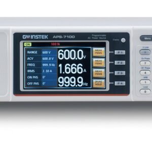
Instek APS-7100 Programmable AC Power Source, 1000 VA, 310 Vrms, 8.4 Arms, 4.3 Inch TFT LCD, APS-7000 Series
Original price was: $3,811.50.$3,620.92Current price is: $3,620.92. Add to cart

Sale

Global Specialties 1420 – Variable AC Power Supply, 0-150 VAC
Original price was: $907.50.$771.37Current price is: $771.37. Add to cart
 Keithley 2601B-PULSE – S...
 Original price was: $18,370.00.$17,820.00Current price is: $17,820.00.
Our team of knowledgeable professionals is here to help you make informed decisions. Whether you need product recommendations, technical support, or guidance on your purchase, we're just a click away.
Contact Us Now:
📧 sales@nestesinstruments.com
📞 +1 (833) 763-7837
Let us assist you in finding the perfect solution!
Contact Us Now:
📧 sales@nestesinstruments.com
📞 +1 (833) 763-7837
Let us assist you in finding the perfect solution!
Reviews
There are no reviews yet.