No products in the cart.
Sale


Description
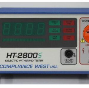
Compliance West HT-2800S Hipot Tester, 0-2800Vdc 5mA, Adjustable Ground Continuity UL Listed

Hipot Tester, 0-2800Vdc @ 5mA and Adjustable Ground Continuity, UL Listed!
- Economical, durable and compact
- Calibration certificate included
- One year calibration cycle
- One year warranty
The newest product of our Hipot Line Testers, the UL Listed HT-S series hipot now comes with an adjustable ground continuity test in range of 0.08 – 1.50 Ω, and Auto-offset for test leads up to 1.00 Ω. Performs 0-2800 DC Hipot Test. Neutral/Hot to Ground Leakage current test up to 5 mA DC. Easy to use and connect. Ships complete with cables, manual, and a Calibration Certificate. Made in the USA. Calibration and repair services available.
Front Panel Features

Front Panel Controls, Indicators and Connectors for HT-3000S, HT-2800S and HT-2000S
| ITEM | NAME | FUNCTION |
| 1 | RESET Button / Red Indicator | When lit, indicates that the HT-S tester is unarmed. This button must be pushed before the TEST button is functional. When the RESET button is pressed, the red RESET indicator goes out and the yellow TEST indicator is lit. PRESSING THE RESET BUTTON AT ANY TIME STOPS THE TEST. |
| 2 | TEST Button / Yellow Indicator | When lit, indicates that the HT-S tester is ready to test the connected equipment. The yellow TEST indicator goes out when the TEST button is pressed. |
| 3 | Voltage Meter | Provides visual indication to the operator of the actual output voltage of the HT-S tester. Used to set the test voltage level during the setup procedure. |
| 4 | Ramp Bar Graph LED’s | Individual LED’s light in sequence from left to right as the test voltage ramps from zero to full voltage. LED’s turn off (ramp back down) at end of test. |
| 5 | Hipot Pass LED | At the end of the preset high voltage duration time, if no failures are encountered, the green light will light and the test will terminate. |
| 6 | Full Voltage LED | If full voltage is successfully reached, the Full Voltage LED will light and the high voltage duration timer starts. |
| 7 | Ground OK / Ground Open LED’s | Indicates result of Ground Continuity test between grounding pin of the line cord and exposed metal parts of the equipment under test. If the ground path resistance it is higher than the indicated on the ground setting, or if the leads are not properly connected, the red Ground Open LED will light, the internal buzzer will sound, and the test will be terminated. If the ground circuit resistance is acceptable, the green continuity LED will light and the test will continue. If the Ground Check switch is defeated by the operator, both LED’s will be lit for the duration of the test. |
| 8 | Excess Leakage LED | Indicates failure of leakage current test. If leakage current between the primary circuit and ground is higher than the preset value, the red LED will light, the internal buzzer will sound, and the test will be terminated. |
| 9 | Hipot Fail LED | Indicates failure of high voltage test. If arcing or a flashover of the insulation system between primary parts and ground is encountered, the red breakdown LED will light, the internal buzzer will sound, and the test will be terminated. |
| 10 | Return Lead Receptacle | Grounded banana plug receptacle. The 18 AWG Test Return Lead provided is connected here. |
| 11 | High Voltage Device Receptacle | NEMA 5-15R orange receptacle. For connection of the equipment under test. See items 11a and 11b for slots description. |
| 11a | High Voltage Output | On the NEMA plug, the two top vertical slots are tie together, the high voltage to perform the Dielectric Withstand test comes true these two slots. |
| 11b | Ground Continuity Measurement Point | On the NEMA plug, the bottom round slot is the ground continuity measured point. Ground continuity test circuit is measured from this slot (Item 11b) to the Return Lead Receptacle (Item 10). |
| 12 | High Voltage Test Jack | Red High Voltage jack. For connection of high voltage test lead for testing insulating materials, etc. This High Voltage Jack is standard on models HT4200S and HT-3000S, and optional on models HT-2800S and HT-2000S |
| 13 | AC/DC Switch | Selects AC or DC output. Changing switch setting does not change output until the next time the Reset button is pushed. This option is only available on HT-3000S & HT-4200S model. |
Rear Panel Features

Rear Panel Controls, Indicators and Connectors
| ITEM | NAME | FUNCTION |
| 1 | Appliance Inlet / Fuse holder / Power Switch | Use supplied cord set to connect tester to appropriate source of supply. Replace line fuse. Turn Tester ON/OFF. Power switch must be accessible during operation |
| 2 | Fuse replacement warning / Rating of supply | Specifies replacement fuse and required supply voltage. |
| 3 | Testlink OUTPUT Receptacle | The Output Testlink Cableset lead is connected here. The cableset is included when you get Testlink option. |
| 4 | Testlink RETURN Receptacle | The Return Testlink Cableset lead is connected here. The cableset is included when you get Testlink option. |
| 5 | Testlink | Allows connection with GF-30AC-T for Ground Bond Test. A cableset is included when you get this option. ; |
| 6 | Interlock | This is a safety feature, when in short-circuited the HT works regular, when open stops immediately its function. |
| 7 | Relay Interface | Relay Interface/PLC Interface. Test signals through relay contacts/coils (Optional). |
| 8 | Ground Check Switch | Enables or disables the Ground Continuity test. Turn ON for use with three-wire (grounded) power supply cords. Turn OFF for use with two-wire power supply cords. (When ON, conducts Ground Continuity test between the chassis and the grounding pin of the line cord of the equipment being tested. When OFF, Ground Continuity test is bypassed for testing of double-insulated equipment and other types of equipment without a grounding pin in the line cord.) |
| 9 | Ground Resistance Setting Adjustment | Used to adjust the Ground Continuity pass/fail point setting. See “Ground Continuity” on the Adjustment section for more information |
| 10 | Ground Offset Button | This button can perform two different functions. Pressing and holding it for 1 second, the HT-S will measure and display on the front display the Ground Continuity resistance of the EUT under test. Pressing and holding the button for 5 seconds will compensate the resistance of the test cables of fixture, see “Ground Continuity Offset Adjustment” and “Ground Continuity Resistance Measurement” sections for more details. |
| 11 | Leakage Limit Adjustment | Used to adjust the trip level for the excessive leakage current test. See “Leakage Current Level” on Adjustment section for more information. |
| 12 | Test Time Adjustment | Used to adjust high voltage test duration. See “Adjustment of the High Voltage Test Duration” section for this procedure. |
| 13 | Ramp Time Adjustment | Used to adjust the amount of time used to increase the high voltage from zero volts to the required level. See “High Voltage Ramp Time” on Adjustment section for correct procedure. |
| 14 | Directions | Provides directions for tester operation to test personnel. |
| 15 | Voltage Adjust | Used to adjust the High Voltage output. See “High Voltage Level” on the Adjustment section for correct procedure. |
| 16 | Calibration resistor | This resistor (optional) may be used to verify the leakage current. |
Safety Testing / Surge Testing/Hipot Tester Template | |
|---|---|
| Test Type Hipot | DC |
| Max DC Test Voltage | 2800 V (2.8 kV) |
| Max Trip Current DC Test | 5 mA |
Product General Attributes | |
| Warranty | 1 YEARS |
| Safety Approval | CSA, UL |
| Product Height | 7.00 IN |
| Product Length | 12.00 IN |
| Product Width | 12.00 IN |
| Shipping Height | 7.00 IN |
| Shipping Length | 12.00 IN |
| Shipping Width | 12.00 IN |
You must be logged in to post a review.
Manuals/Guides
| Dimensions | 12 × 12 × 7 in |
|---|
Related products


 Compliance West HT-2800S Hipot...
 Original price was: $1,859.00.$1,810.71Current price is: $1,810.71.
Our team of knowledgeable professionals is here to help you make informed decisions. Whether you need product recommendations, technical support, or guidance on your purchase, we're just a click away.
Contact Us Now:
📧 sales@nestesinstruments.com
📞 +1 (833) 763-7837
Let us assist you in finding the perfect solution!
Contact Us Now:
📧 sales@nestesinstruments.com
📞 +1 (833) 763-7837
Let us assist you in finding the perfect solution!
Reviews
There are no reviews yet.