No products in the cart.
Sale

Description

Keithley KTTI-RS232
- Provides instruments with an accessory card slot with an RS-232 interface
- Provides six independently configurable digital input/output lines that can be used to control external digital circuitry
- Digital I/O port is a standard female DB-9 connector
- Can generate output trigger pulses and detect input trigger pulses
- I/O connector: DB-9, female connector
Communication and Digital I/O
The KTTI-RS232 Communication and Digital I/O Accessory provides instruments with an accessory card slot with an RS-232 interface.
The card provides six independently configurable digital input/output lines that can be used to control external digital circuitry, for example, a handler that is used to perform binning operations. The digital I/O port is a standard female DB-9 connector. You can also use these lines for triggering. The instrument can generate output trigger pulses and detect input trigger pulses.
Making Connections
The RS-232 serial port can be connected to the serial port of a controller using a straight-through RS232 cable terminated with DB-9 connectors. Do not use a null modem cable.
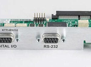
The serial port uses the transmit (TXD), receive (RXD), and signal ground (GND) lines of the RS232 standard. The figure below shows the rear panel connector for the RS232 interface. The table below shows the pinouts for the connector.
Configuration
The baud rate is the rate at which the instrument and the attached device communicate. The factory-selected
baud rate is 9600, but you can choose from any of these available rates.
- 115200
- 57600
- 38400
- 19200
- 9600
- 4800
- 2400
- 1200
- 600
- 300
When you choose a baud rate, make sure the attached device can support the selected rate. The instrument
and the attached device must be configured for the same baud rate.
To configure the RS-232 card:
1. Press the MENU key.
2. Select Communication.
3. Set the Baud Rate option.
4. Set Flow Control.
Digital I/O
The KTTI-RS232 digital I/O port provides six independently configurable digital input/output lines.
You can use these lines for digital control by writing a bit pattern to the digital I/O lines. Digital control is used for applications such as providing binning codes to a component handler. Digital control uses the state of the line to determine the action to take.
You can also use these lines for triggering by using the transition of the line state to initiate an action. The instrument can generate output trigger pulses and detect input trigger pulses. Triggering is used for applications such as synchronizing the operations of a measurement instrument with the operations of other instruments.
You cannot configure or directly control the digital I/O lines from the front panel. To configure and control any of the six digital input/output lines, you need to send commands to the KTTI-RS232 over a remote interface. You can use either the SCPI or TSP command set.
See Remote communications interfaces in the instrument reference manual for information about setting up a remote interface and choosing a command set.
Digital I/O connector and pinouts
The digital I/O port uses a standard female DB-9 connector, located on the rear panel of the KTTI-RS232. You can connect to the KTTI-RS232 digital I/O using a standard male DB-9 connector. The port provides a connection point to each of the six digital I/O lines and other connections.
Product General Attributes | |
|---|---|
| Safety Approval | CE |
| Product Height | 2.54 IN |
| Product Length | 4.72 IN |
You must be logged in to post a review.
Manuals/Guides
Manuals
| Dimensions | 4.72 × 2.54 in |
|---|
Related products


Sale

Televes 148883 – Ellipse Mix U/V-Hi Antenna
Original price was: $186.94.$175.94Current price is: $175.94. Add to cartSale

Televes 560383 – Kit: Mast Amplifier with BOSS-Tech and “F” Power Supply Unit (Repack Ready)
Original price was: $87.94.$76.94Current price is: $76.94. Add to cart
 Keithley KTTI-RS232 – Co...
 Original price was: $427.90.$406.50Current price is: $406.50.
Our team of knowledgeable professionals is here to help you make informed decisions. Whether you need product recommendations, technical support, or guidance on your purchase, we're just a click away.
Contact Us Now:
📧 sales@nestesinstruments.com
📞 +1 (833) 763-7837
Let us assist you in finding the perfect solution!
Contact Us Now:
📧 sales@nestesinstruments.com
📞 +1 (833) 763-7837
Let us assist you in finding the perfect solution!
Reviews
There are no reviews yet.