No products in the cart.


Description
Adash America A3816 – 16 Channel A3800 Compact On-line Monitoring

- 4 – 16 channels AC
- 4 – 16 channels DC
- 1 – 4 TACHO inputs
- Optional number of input channels
- Compact size, DIN rail mounting
- Adaptive algorithm of data acquisition
The A3800 is a compact size on-line monitoring and diagnostic system designed to increase machine reliability. The compact size of the A3800 enables it to be placed directly on the DIN rail in the switchboard.
The A3800 unit has an optional number of AC and DC input channels – 4, 8, 12, or 16. AC and DC channels are separate. This means that the 4-channel configuration allows you to connect 4 AC and 4 DC channels. Depending on the number of active input channels, we can use 1 – 4 independent TACHO inputs. The number of active channels can be extended additionally by purchasing additional licenses.
Each group of 4 channels allows fully simultaneous measurements. Groups of 4 input channels are switched to each other via a multiplex.
The A3800 unit can be used also as a powerful multichannel analyzer. The setting and control of A3800 unit is done in DDS software.
Set up and control

The setup and control of the A3800 is done by the DDS software. The set up has never been easier. The only thing you need to do is to create the tree of machines, measurement points, and required readings and assign them to appropriate channels. Then you just press START and the readings are taken automatically.
The new data acquisition control system was developed for the A3716 and A3800 systems. Now the units read the vibration continuously, not only at predefined time intervals. The adaptive algorithm saves the readings to the database.
The A3800 unit continuously monitors the required machines and adaptively saves the readings to the data storage computer. The data is accessible from various workstations for control and analysis.
The great advantage of the DDS software is its very easy set-up. There is no difficult installation of the server anymore and no complicated set-up of parameters. The demands for transfer and data storage are minimized.
Application Scheme of a 3800 Units

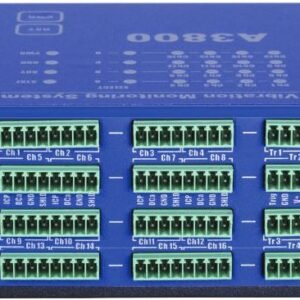
A3800 – Top Panel

The connectors for connecting the sensors are located on the top panel. Connectors are divided into groups A, B, C, D.
Group A: AC and DC channels 1 – 4, TACHO input 1.
Group B: AC and DC channels 5 – 8, TACHO input 2.
Group C: AC and DC channels 9 – 12, TACHO input 3.
Group D: AC and DC channels 13 – 16, TACHO input 4.
Input ranges:
AC input: +/- 12 V peak – peak
DC input: +/- 24 V or 4 – 20 mA
TACHO +10 V
In this picture you can see top panel with installed plug-ins.

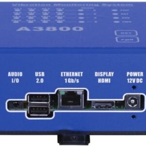
A3800 – Bottom Panel

Legend:
AUDIO I/O: socked for audio 3.5 jack.
USB 2.0: two USB ports.
ETHERNET: socked for Ethernet connection.
DISPLAY: HDMI display connection.
POWER: socked for 12 V DC powering.
A3800 Unit Description
A3800 – Front panel

Legend:
Channels LEDs indicate on which channels the measurement is defined.
Green color … indicates good condition of the channel input, sensor and cable.
Flashing red color … indicates sensor or cable error.
Groups LEDs indicate which channel group is active for measurement.
Orange color … indicates active group.
Status LED indicates status of A3800 DSP board.
Fast flashing green color (four times per sec) … measurement is running.
Slow flashing green color (one time per sec) … waiting for measurement
Red color … DSP board error.
Ready LED indicates status of A3800 control board.
Green color … control board OK.
Red color … control board error.
HDD LED indicates r/w operation on HDD.
Red color … r/w operation in progress.
Power LED indicates power on of A3800 unit.
Green color … A3800 unit is power on.
Reset button … press and hold for at least 5 seconds to reset control board.
Power button … press and hold for at least 5 seconds to switch ON/OFF A3800 unit.
Application Scheme

None
You must be logged in to post a review.
Manuals/Guides
ManualsSpec Sheets
Related products

Sale

SKF CMSS 200-02-SL Machine Condition Indicator
Original price was: $1,209.47.$614.05Current price is: $614.05. Add to cart

 Adash America A3816 – 16...
Our team of knowledgeable professionals is here to help you make informed decisions. Whether you need product recommendations, technical support, or guidance on your purchase, we're just a click away.
Contact Us Now:
📧 sales@nestesinstruments.com
📞 +1 (833) 763-7837
Let us assist you in finding the perfect solution!
Contact Us Now:
📧 sales@nestesinstruments.com
📞 +1 (833) 763-7837
Let us assist you in finding the perfect solution!
Reviews
There are no reviews yet.