No products in the cart.

Description

Compliance 00-5000PACDC-200mA
- Test time, and leakage limit are settable.
- Test duration timer is defeatable for specialized testing.
- Test results are determined quickly, without operator intervention.
- Testing may be terminated or continued when a dielectric breakdown is detected.
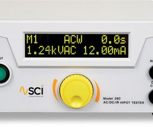
Hipot Tester, 0-5000V AC 200mA
A 5000V AC/ 6000VDC hipot tester that’s easy to use and priced right. Select AC or DC output via front panel button. Simple for production line personnel, easy to set up. Designed so that operator can defeat the leakage current limit and dielectric breakdown shutoffs to allow troubleshooting and analysis of problems with the DUT. Includes precision leakage current and test time setup and viewing from the LED meter. Adjustment is made with no HV output.
An Introduction to Dielectric Withstand Testing with the HT-5000P ac/dc 200mA
The dielectric withstand test is a test which is recognized by safety agencies worldwide as a valid criterion of safe assembly of end-use equipment. The HT-5000P ac/dc 200mA is designed as a research instrument to determine the dielectric properties of component assemblies of end-use equipment. It applies a high-voltage potential between Output and Return test leads and monitors Leakage Current, and watches for Dielectric Breakdown during the test. To aid in testing, the HT-5000P ac/dc 200mA can be configured with or without a test duration timer, and can be set to deliver high voltage after an arc has been detected to pinpoint an area of arcing.
The dielectric withstand test involves high voltage, and caution should be exercised when using the HT-5000P ac/dc 200mA. The Return Receptacle on the front panel is connected to ground potential, and setups should be designed with this in mind, to guard against the operator contacting high voltage. Always make sure the return lead is firmly connected.
Leakage Test
The HT-5000P ac/dc 200mA leakage test uses a separate low-frequency circuit to detect excessive current between the Output and Return receptacles on the front panel. There is not a specific leakage current level pass/fail requirement at this time for most equipment. However, higher than normal leakage current on a particular sample may indicate an assembly, and or a component problem in the circuit.
The leakage current is also monitored by the HT-5000P ac/dc 200mA to ensure that excessive leakage does not keep the tester from developing full voltage required for the high voltage test. The HT-5000P ac/dc 200mA will provide full voltage at any leakage current level up to 200mA. Set the acceptable leakage current limit using the Shutdown Limit Potentiometer on the front panel.
If the green Full Voltage indicator lights and the test continue, the leakage current was below the acceptable limit. If the red Excess Leakage indicator lights, the buzzer sounds, and the test is terminated; the leakage current was above the acceptable limit.
High Voltage Dielectric Withstand Test
This test checks for insulation system breakdown’s by applying a high voltage between the Output and Return receptacles on the front panel. The HT-5000P ac/dc 200mA uses a separate high-frequency circuit to detect arc breakdowns.
Set the test duration with the Timer Control Potentiometer on the front panel. The test time is counted from the time the Full Voltage indicator is lit to the completion of the test. The Timer Control Switch must be set to ON, or the HT-5000P ac/dc 200mA will test only while the Test Button is pressed. The minimum test time is one second regardless of the setting of the Timer Control Switch.
If the green Hipot Pass indicator lights, the test cycle has been successfully completed, meaning there was no dielectric breakdown. If the red Hipot Fail indicator lights, a breakdown arc has been detected.
High Voltage Discharge
The HT-5000P ac/dc 200mA has an internal circuit designed to remove the high voltage, after completion of the dielectric withstand test. The HT-5000P ac/dc 200mA should remain connected to the circuit until the front panel meter shows that the output voltage has dropped to a safe level.
Front Panel Controls, Indicators and Connectors

| ITEM NO. | NAME | FUNCTION |
| 1. | HIPOT | When ON, Dielectric breakdown detect will be activated. When in DEFEAT position, test will continue regardless of a dielectric breakdown, but it can be stopped by the excess leakage limit. NOTE: The TIMER switch must also be in the DEFEAT position, otherwise the buzzer will sound. The test will continue only as long as the TEST button is pressed. Minimum test time is approximately one second. |
| 2. | TIMER | When ON, test duration is set by TIMER ADJUST, Item 4. When in DEFEAT position, testing continues only as long at TEST button is pressed. Minimum test time is one second. NOTE: TIMER Switch position must be DEFEAT when HIPOT Switch is in the DEFEAT position. |
| 3. | LEAKAGE ADJUST | Adjusts the shutdown point for the Leakage Current Test. For details see “Leakage Current Adjust.” |
| 4. | TIMER ADJUST | Adjusts the test duration. For details see “Test Time Adjust”. |
| 5. | RESET Button | When lit, indicates that the HT-5000P ac/dc 200mA is unarmed. When the RESET button is pressed, the TEST switch is lit. PRESSING THE RESET BUTTON AT ANY TIME IMMEDIATELY STOPS TESTING. |
| 6. | TEST Button | When lit, indicates the HT-5000P ac/dc 200mA is ready to test; press to begin testing. NOTE: The Voltage Adjust knob must be at the minimum position in order to disarm the Zero Voltage Start safety feature, Item 15. |
| 7. | VOLTAGE METER | Connected to the output. Reads actual output voltage. Adjust meter range with VOLTAGE ADJUST Knob, Item 15. |
| 8. | HIPOT PASS LED | Indicates test conclusion with satisfactory results. |
| 9. | FULL VOLTAGE LED | Lights when output voltage has ramped up. Test time starts when this indicator lights. |
| 10. | HIPOT FAIL LED | Lights when arcing or insulation flashover has occurred. |
| 11. | EXCESS LEAKAGE LED | Actual leakage current has exceeded the shutdown point set with Shutdown Limit Potentiometer, Item 3. |
| 12. | CURRENT METER | Connected to the output. Read the current flowing through the return lead of the HT-5000P ac/dc 200mA during the test. |
| 13. | HIGH VOLTAGE output jack | Connect high voltage lead here to conduct an AC & DC test. |
| 14. | RETURN Receptacle | At chassis ground reference level. Connect black return lead here. |
| 15. | VOLTAGE ADJUST Knob | Voltage is continuously adjustable before or during testing with this knob. NOTE: Before the test can commence, the Zero Voltage Start safety feature most be disarmed by turning the voltage knob to the minimum. |
| 16. | AC POWER Switch | Energizes the HT-5000P ac/dc 200mA. |
| 17. | AC/DC Switch | Selects AC or DC output. Changing switch setting does not change output until the next time the Reset button is pushed. |
Safety Testing / Surge Testing/Hipot Tester Template | |
|---|---|
| Test Type Hipot | AC, DC |
| Max AC Test Voltage | 5000 V (5 kV) |
| Max DC Test Voltage | 7000 V (7 kV) |
| Min AC Test Voltage | 0 V |
| Min DC Test Voltage | 0 V |
| Max Trip Current AC Test | 200 mA |
| Min Trip Current AC Test | 5 mA |
| Max Trip Current DC Test | 200 mA |
| Min Trip Current DC Test | 5 mA |
Product General Attributes | |
| Product Weight | 90 LBS |
| Shipping Weight | 95 LBS |
| Power Supply Voltage | 120V 50/60 Hz |
| Shipping Height | 15.00 IN |
| Shipping Length | 21.00 IN |
| Shipping Width | 21.00 IN |
You must be logged in to post a review.
Manuals/Guides
| Weight | 90 lbs |
|---|
Related products


 Compliance 00-5000PACDC-200mA ...
Our team of knowledgeable professionals is here to help you make informed decisions. Whether you need product recommendations, technical support, or guidance on your purchase, we're just a click away.
Contact Us Now:
📧 sales@nestesinstruments.com
📞 +1 (833) 763-7837
Let us assist you in finding the perfect solution!
Contact Us Now:
📧 sales@nestesinstruments.com
📞 +1 (833) 763-7837
Let us assist you in finding the perfect solution!
Reviews
There are no reviews yet.