No products in the cart.

Description
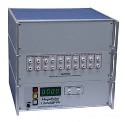
Compliance 1.2×50-10P – PV PV Testing Up to 10kV, Up to 180nF Panels
- Virtual Impedance of 12 ohms
- Outputs a 1.2x50uSec waveform for testing of Photovoltaic Panels, corrected for panel capacitance.
- Front panel switch allows waveform reversal
- Provides correct waveform for any panel 10 – 100 nF; taps provided for 100-180 nF are for Reference Only. Can be controlled from computer with Option Testminder.
The MegaPulse 1.2×50-10kV PV is specifically designed to perform the Input Test on PV Panels in accordance with IEC 61730-2, Para. 10.5.3. The output is in accordance with the published waveform from 800-10000V peak (open circuit).
IEC 61730-2 stipulates that an in-tolerance 1.2x50mSec waveform be delivered to the PV Panel during testing. The MegaPulse 1.2×50-10P PV is provided with output taps corresponding to the capacitance of the PV panel being tested.
Complies with IEC 61730-2 Para. 10.5.3 and IEC 1180 tolerances for a 1.2×50 waveform when testing a PV panel with a capacitance range from 10nF – 100nF. Taps from 100nF – 180nF are provided for reference testing only.
Front and Rear Panel Features
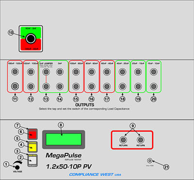
Controls, Indicators, Connectors – MegaPulse 1.2×50-10P PV Front Panel
| ITEM | NAME | FUNCTION |
| 1 | VOLTAGE Adjust Knob | Turn Clockwise to increase the output voltage after the CHARGE button has been pressed. Turn the knob fully counterclockwise (lowest voltage setting) before the start of each test, and afterthe end of each test. |
| 2 | POLARITY switch | The polarity switch only operates when the CHARGE indicator is lit, i.e. the output is not charged. The polarity of the output waveform can be changed by pressing the POLARITY switch on the front panel. Press this switch to toggle the output polarity from Normal to Reverse. The polarity is Normal when the NOR indicator is lit. In this case, the High Voltage will appear on the OUTPUT as a positive pulse relative to the RETURN jack. When the polarity switch is in the Reverse position (REV indicator is lit), the High voltage will appear on the OUTPUT as a negative pulse relative to the RETURN jack. |
| 3 | NOR REV indicator | Indicates the state of the Output Polarity switch. NOR indicates Normal position. REV indicates Reverse position. |
| 4 | CHARGE switch | Press this switch to begin charging the impulse storage capacitor. The CHARGE indicator will turn off after the CHARGE switch is pressed, and the TRIGGER indicator will turn on. The voltage on the capacitor will appear on the voltage meter, Item 8. This voltage will appear across the output leads when the TRIGGER switch is pressed. Note that the POLARITY switch is prevented from operating after the CHARGE switch has been pressed. |
| 5 | CHARGE indicator | This Yellow indicator is lit to show that pressing the CHARGE switch is the next logical step in a test sequence. Pressing the Charge switch causes the CHARGE indicator to go out. |
| 6 | TRIGGER switch | Press this switch (after pressing the CHARGE switch to charge the storage capacitor) to trigger the output impulse waveform. The impulse waveform will appear across the output leads. |
| 7 | TRIGGER indicator | This Red indicator is lit to show that pressing the TRIGGER switch is the next logical step in a test sequence. This indicator will turn on after the CHARGE switch is pressed, and will remain on until the TRIGGER switch is pressed. Pressing the TRIGGER switch causes the TRIGGER indicator to go out. |
| 8 | VOLTAGE meter | Displays the output voltage set point. This voltage is the theoretical open-circuit peak voltage that will appear across the output leads when the trigger button is pressed. The voltage reading will increase from zero to the voltage set point when the Charge switch is pressed. Note that the Voltage meter may indicate that some residual voltage is present on the main storage capacitor, even when the tester is first turned ON. This is due to inherent charging of the internal capacitors. Pressing the TRIGGER switch will discharge the capacitors (be sure not to touch the output and return leads when pressing the trigger switch). Note that the peak amplitude of the measured output waveform is proportional to the voltage that is read on the front panel of the MegaPulse, but it will always be somewhat lower. This is because the meter on the MegaPulse is measuring the voltage on the main impulse storage capacitor. This voltage will intentionally dissipate to some extent before reaching the output leads. |
| 9 | RETURN jacks | This is the return for the impulse waveform. These jacks are referenced to the chassis of the MegaPulse, and are referenced to earth ground as long as the MegaPulse is properly grounded. Even though these jacks are referenced to ground, they should be treated as hazardous whenever the MegaPulse is turned ON. |
| 10 | Green or Red Output Jacks switch selector | When the red outputs jacks will be used (180nF – 40nF), set switch to red position. When the green outputs jacks will be used (40nF – 0nF), set switch to green position. |
| 11 | 180–122nF Output Jacks | Pair of output jacks for testing TUV with capacitance between 180nF and 122nF. Item 10 must be selected to red position. |
| 12 | 122–100nF Output Jacks | Pair of output jacks for testing TUV with capacitance between 122nF and 100nF. Note: Item 10 must be selected to red position. |
| 13 | OnF JUMPER | Jumper jacks to configure properly the 0nF Output Jacks mention on Item 14. Note: Item 10 must be selected to green position. |
| 14 | 0nF Output Jacks | Pair of output jacks for testing TUV with capacitance between 122nF and 100nF. Note 1: Item 10 must be selected to green position. Note 2: Item 13 must be placed. |
| 15 | 100–80nF Output Jacks | Pair of output jacks for testing TUV with capacitance between 100nF and 80nF. Note: Item 10 must be selected to red position. |
| 16 | 80–60nF Output Jacks | Pair of output jacks for testing TUV with capacitance between 80nF and 60nF. Note: Item 10 must be selected to red position. |
| 17 | 60–40nF Output Jacks | Pair of output jacks for testing TUV with capacitance between 60nF and 40nF. Note: Item 10 must be selected to red position. |
| 18 | 40–25nF Output Jacks | Pair of output jacks for testing TUV with capacitance between 40nF and 25nF. Note: Item 10 must be selected to green position. |
| 19 | 25–15nF Output Jacks | Pair of output jacks for testing TUV with capacitance between 25nF and 15nF. Note: Item 10 must be selected to green position. |
| 20 | 15–10nF Output Jacks | Pair of output jacks for testing TUV with capacitance between 15nF and 10nF. Note: Item 10 must be selected to green position. |
| 21 | 1000:1 BNC jack (optional) | (Optional) 1000:1 voltage output for connection to an oscilloscope. The signal can be used for reference viewing of the waveform as delivered to the EUT. It is not correct in the time domain, so the output is for a rough approximation of the waveform and is best for verification that a waveform was delivered to the EUT. |
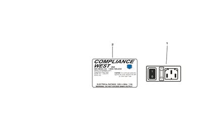
Controls, Indicators, Connectors – MegaPulse 1.2×50-10P PV Rear Panel
| ITEM | NAME | FUNCTION |
| 1 | Appliance Inlet /Fuseholder / Power Switch | Use supplied cordset to connect the MegaPulse 1.2×50-7P tester to an appropriate source of supply. Fuse holder provides access for Fuse replacement, and the Power Switch is used to turn the tester ON and OFF. |
| 2 | Fuse replacement warning / Rating of supply | Specifies replacement fuse and required supply voltage. |
Product General Attributes | |
|---|---|
| Shipping Weight | 50 LBS |
| Shipping Height | 17.00 IN |
| Shipping Length | 17.00 IN |
| Shipping Width | 11.00 IN |
You must be logged in to post a review.
Manuals/Guides
ManualsSpec SheetsOther
- Compliance 1.2x50-10P PV Waveforms Actual Vpeak-rev 800 90nF
- Compliance 1.2x50-10P PV Waveforms Actual Vpeak-rev 800 70nF
- Compliance 1.2x50-10P PV Waveforms Actual Vpeak-rev 800 50nF
- Compliance 1.2x50-10P PV Waveforms Actual Vpeak-rev 800 30nF
- Compliance 1.2x50-10P PV Waveforms Actual Vpeak-rev 800 0nF BNC
- Compliance 1.2x50-10P PV Waveforms Actual Vpeak-rev 800 0nF
- Compliance 1.2x50-10P PV Waveforms Actual Vpeak-rev 10k 90nF
- Compliance 1.2x50-10P PV Waveforms Actual Vpeak-rev 10k 70nF
- Compliance 1.2x50-10P PV Waveforms Actual Vpeak-rev 10k 50nF
- Compliance 1.2x50-10P PV Waveforms Actual Vpeak-rev 10k 30nF
- Compliance 1.2x50-10P PV Waveforms Actual Vpeak-rev 10k 20nF
- Compliance 1.2x50-10P PV Waveforms Actual Vpeak-rev 10k 0nF BNC
- Compliance 1.2x50-10P PV Waveforms Actual Vdur-800 70nF
- Compliance 1.2x50-10P PV Waveforms Actual Vdur-800 50nF
- Compliance 1.2x50-10P PV Waveforms Actual Vdur-800 30nF
Related products


 Compliance 1.2×50-10P PV ...
Our team of knowledgeable professionals is here to help you make informed decisions. Whether you need product recommendations, technical support, or guidance on your purchase, we're just a click away.
Contact Us Now:
📧 sales@nestesinstruments.com
📞 +1 (833) 763-7837
Let us assist you in finding the perfect solution!
Contact Us Now:
📧 sales@nestesinstruments.com
📞 +1 (833) 763-7837
Let us assist you in finding the perfect solution!
Reviews
There are no reviews yet.