No products in the cart.
Sale

Description
Compliance 968-B – Power Line Power Line Tests 2x10s 2500V 1000A Waveform

- Reverse polarity waveforms available by pushing a button on the front panel. No need to change the test setup. Positive polarity indication minimizes errors.
- Front panel voltage meter shows residual voltage in charging circuit for safer operation.
- 1-year calibration cycle.
Provides correct waveform for any panel 10 – 100 nF; taps provided for 100-180 nF are for Reference Only. Can be controlled from computer with Option Testminder.
Designed to generate the surge test described in Clause 68.302(d) Power Line Surge. Output voltage is 2500 volts minimum, peak short circuit current is 1000 amperes minimum. A switch is provided for reversal of output polarity. Optional divider network available for oscilloscope connection. This MegaPulse tester has isolated outputs; that is, no ground reference.
The waveform generated is 2×10/2×10, Vp=2500V. To test, the front panel meter is set to 2500V.
A coupling/decoupling network is required to provide isolation between the DUT, the MegaPulse Power Line and the mains power when the pulse is applied. We can supply our CDN 240/15, built to the requirements of EN61000-4-5 and for use on single phase circuits up to 240Vac and up to 15 amps.
Fuse Replacement
There is a user-replaceable fuse (F1) located on the rear panel of the instrument. It is located behind a door in the Power Inlet-Power Switch-Fuse Holder device. The fuse rating is noted on the rear panel. Do not attempt to replace it with a fuse of any other rating.
Use the following procedure to replace the fuse F1:
- Turn the power switch to the O or off position.
- Unplug the instrument from the source of supply.
- Remove the power inlet cord from the instrument.
- Using a small screwdriver, pry open the fuse holder door.
- Replace the fuse with a new one of the correct rating.
- Replace the fuse holder door and power inlet cord.
Front and Rear Panel Features
Before using your tester, take a few minutes to become familiar with the use of its controls, indicators and connectors.

Controls, Indicators, Connectors – Front Panel
| ITEM | NAME | FUNCTION |
| 1 | VOLTAGE Adjust Knob | Turn Clockwise to increase the output voltage after the CHARGE button has been pressed. Turn the knob fully counterclockwise (lowest voltage setting) before the start of each test, and afterthe end of each test. |
| 2 | POLARITY switch | The polarity switch only operates when the CHARGE indicator is lit, i.e. the output is not charged. The polarity of the output waveform can be changed by pressing the POLARITY switch on the front panel. Press this switch to toggle the output polarity from Normal to Reverse. The polarity is Normal when the NOR indicator is lit. In this case, the High Voltage will appear on the OUTPUT as a positive pulse relative to the RETURN jack. When the polarity switch is in the Reverse position (REV indicator is lit), the High voltage will appear on the OUTPUT as a negative pulse relative to the RETURN jack. |
| 3 | NOR REV indicator | Indicates the state of the Output Polarity switch. NOR indicates Normal position. REV indicates Reverse position. |
| 4 | CHARGE switch | Press this switch to begin charging the impulse storage capacitor. The CHARGE indicator will turn off after the CHARGE switch is pressed, and the TRIGGER indicator will turn on. The voltage on the capacitor will appear on the voltage meter, Item 8. This voltage will appear across the output leads when the TRIGGER switch is pressed. Note that the POLARITY switch is prevented from operating after the CHARGE switch has been pressed. |
| 5 | CHARGE indicator | This Yellow indicator is lit to show that pressing the CHARGE switch is the next logical step in a test sequence. Pressing the Charge switch causes the CHARGE indicator to go out. |
| 6 | TRIGGER switch | Press this switch (after pressing the CHARGE switch to charge the storage capacitor) to trigger the output impulse waveform. The impulse waveform will appear across the output leads. |
| 7 | TRIGGER indicator | This Red indicator is lit to show that pressing the TRIGGER switch is the next logical step in a test sequence. This indicator will turn on after the CHARGE switch is pressed, and will remain on until the TRIGGER switch is pressed. Pressing the TRIGGER switch causes the TRIGGER indicator to go out. |
| 8 | VOLTAGE meter | Displays the output voltage set point. This voltage is the theoretical open-circuit peak voltage that will appear across the output leads when the trigger button is pressed. The voltage reading will increase from zero to the voltage set point when the Charge switch is pressed. Note that the Voltage meter may indicate that some residual voltage is present on the main storage capacitor, even when the tester is first turned ON. This is due to inherent charging of the internal capacitors. Pressing the TRIGGER switch will discharge the capacitors (be sure not to touch the output and return leads when pressing the trigger switch). Note that the peak amplitude of the measured output waveform is proportional to the voltage that is read on the front panel of the MegaPulse, but it will always be somewhat lower. This is because the meter on the MegaPulse is measuring the voltage on the main impulse storage capacitor. This voltage will intentionally dissipate to some extent before reaching the output leads. |
| 9 | OUTPUT jack | The impulse waveform appears on the OUTPUT jack, referenced to the RETURN jack. When the POLARITY switch is in the Normal position (NOR indicator is lit) the output will be a positive pulse. When the POLARITY switch is in the Reverse position (REV indicator is lit) the output will be a negative pulse. There dual identical outputs, one for TIP and the other for RING. |
| 10 | RETURN jacks | This is the return for the impulse waveform. These jacks are referenced to the chassis of the MegaPulse, and are referenced to earth ground as long as the MegaPulse is properly grounded. Even though these jacks are referenced to ground, they should be treated as hazardous whenever the MegaPulse is turned ON. |
| 11 | OUTPUT “L” jack | The impulse waveform appears on the OUTPUT jack, referenced to the RETURN jack. When the POLARITY switch is in the Normal position (NOR indicator is lit) the output will be a positive pulse. When the POLARITY switch is in the Reverse position (REV indicator is lit) the output will be a negative pulse. There dual identical outputs, one for TIP and the other for RING. |

Controls, Indicators, Connectors – MegaPulse 1.2×50-10P PV Rear Panel
| ITEM | NAME | FUNCTION |
| 1 | Appliance Inlet /Fuseholder / Power Switch | Use supplied cordset to connect the MegaPulse 1.2×50-7P tester to an appropriate source of supply. Fuse holder provides access for Fuse replacement, and the Power Switch is used to turn the tester ON and OFF. |
| 2 | Fuse replacement warning / Rating of supply | Specifies replacement fuse and required supply voltage. |
| 3 | Directions | Provides directions for Tester operation to test personnel. |
| 4 | Voltage Adjust | Used to adjust the High Voltage output (as an alternative to the front panel Voltage Adjust knob). Turn Clockwise to increase the output voltage after the CHARGE button has been pressed. Turn the adjustment fully counterclockwise (lowest voltage setting) before the start of each test, and after the end of each test. |
Product General Attributes | |
|---|---|
| Shipping Weight | 25 LBS |
| Shipping Height | 5.25 IN |
| Shipping Length | 17.00 IN |
| Shipping Width | 17.00 IN |
You must be logged in to post a review.
Manuals/Guides
Related products
Sale

Instek GPT-9804 – Performance Hi-Pot Tester, AC 200VA AC/DC Withstanding Voltage/Insulation Resistance/Ground Bond Tester
Original price was: $2,618.00.$2,356.20Current price is: $2,356.20. Add to cart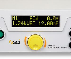

 Compliance 968-B Power Line &#...
 Original price was: $9,130.00.$8,892.86Current price is: $8,892.86.
Our team of knowledgeable professionals is here to help you make informed decisions. Whether you need product recommendations, technical support, or guidance on your purchase, we're just a click away.
Contact Us Now:
📧 sales@nestesinstruments.com
📞 +1 (833) 763-7837
Let us assist you in finding the perfect solution!
Contact Us Now:
📧 sales@nestesinstruments.com
📞 +1 (833) 763-7837
Let us assist you in finding the perfect solution!
Reviews
There are no reviews yet.