No products in the cart.


Description
Extech RPM33
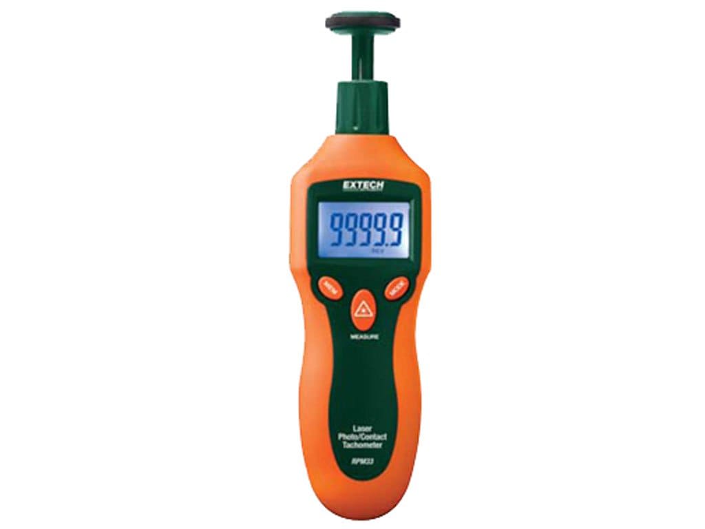
- Readings are displayed on the large five-digit backlit LCD
- Microprocessor based with quartz crystal oscillator to maintain high accuracy
- Store/recall 10 data sets in memory with 4 parameters (measurement, max, min and average)
- Provides wide RPM (photo and contact) and Linear Surface Speed/Length (contact) measurements
- Laser guided for greater distance non-contact measurements up to 1.6ft (500mm)
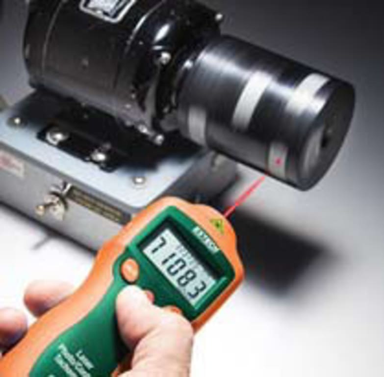
Combination Mini Contact / Laser Photo Tachometer
Quickly measure RPM, surface speed and length with one tool. Use the contact wheel for up-close readings or laser mode for safer, non-contact measurements up to 1.6ft (0.5m) away.
Applications
Contact RPM
- Flywheels
- Conveyors
- Pumps
- Elevators
Non-Contact RPM
- Motors
- Fans
- Gears
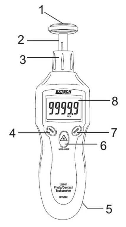
Meter Description
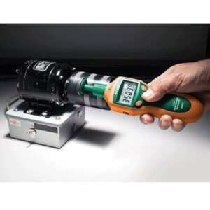
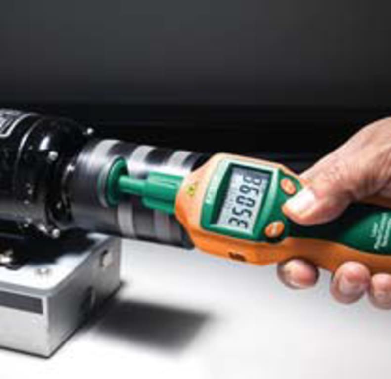
1. Surface (circumference) wheel accessory is shown connected to shaft (rubber cone and concave accessories are also supplied)
2. Adaptor shaft
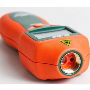
3. Removable collar (Photo sensor and laser source are located at the top of the meter under this collar)
4. MEM (Memory) button
5. Battery compartment (rear)
6. MEASURE button
7. MODE button
8. LCD Display
Push-button Description
- MEM (Memory) button: Used to Record/Recall readings
- MEASURE button: Press and hold to take readings. The Laser pointer will switch on for Photo tachometer measurements when pressed
- MODE button: Press momentarily to switch measurement units. Press and hold for 2 seconds to switch between Surface Speed and Length measurement modes
Preparing for Measurements
Non-Contact (Photo) Tachometer Preparation
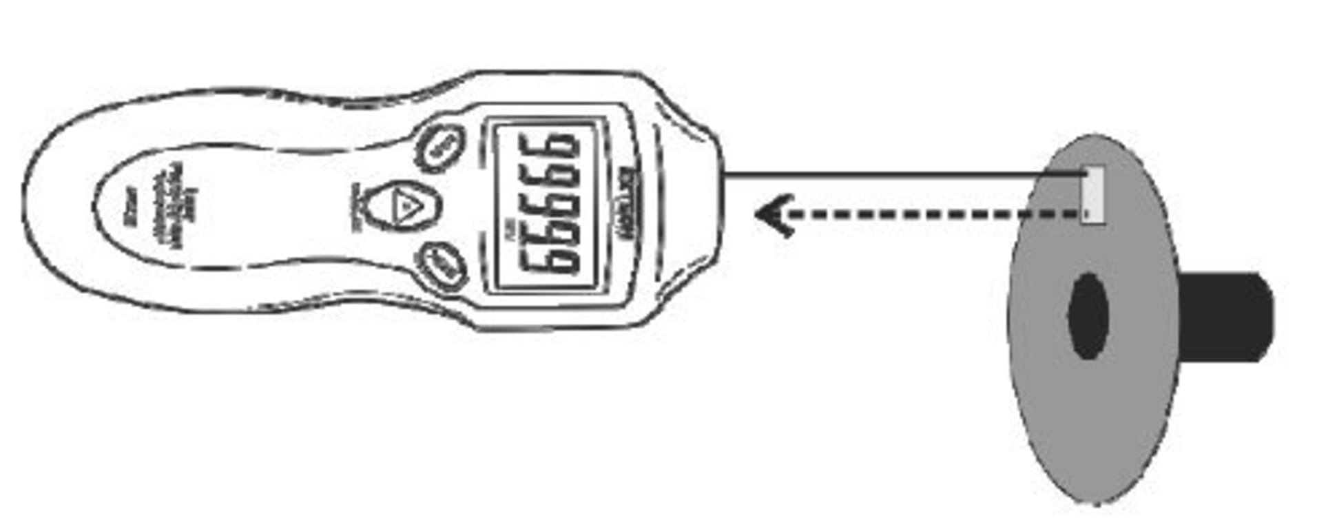
1. Apply a square piece of reflective tape to the surface of the object under test (nominal tape size: 0.5″/12mm). Be sure to affix the tape as close to the outer edge of the object under test as possible. See diagram below.
2. If not already done, unscrew and remove the meter collar (item number 3 in the Description section diagram)
3. Proceed to the “Taking Measurements” section below.
Contact Tachometer Preparation
1. If not already done, attach the collar (item number 3 in the Description section diagram) to the meter.
2. Slide the contact adaptor onto the tachometer’s shaft. Be sure to align the adaptor with the alignment pin on the shaft of the contact adaptor.
3. Attach a contact measurement accessory (cone, wheel, or concave accessory) onto the contact adaptor.
4. For Contact operation the meter can measure Surface Speed or Length. Read the section titled “Surface Speed and Length Measurement Modes” later in this guide for details.
5. Follow the steps in the “Taking Measurements” section below.
Taking Measurements
Non-Contact (Photo) Tachometer Measurements
1. Prepare for the Non-Contact measurement as described in the Measurement Preparation section above.
2. Use the MODE button (momentarily presses) to select RPM (rotations per minute) or Hz (Hertz: rotations per second) as the unit of measure.
3. Press and hold the MEASURE button to begin a measurement session. Hold the MEASURE button down for the duration of the test and release it to end the session.
4. Point the meter toward the device under test at a distance of 2″ to 20″ (50 to 500mm). Be sure to align the laser light beam with the reflective tape (see diagram above in previous section).
5. Verify that the ((( ))) monitor indicator appears on the LCD when the reflective tape passes through the light beam.
6. Read the measurement result from the LCD display.
7. When the MEASURE button is released the last reading will remain on the display for 5 to 10 seconds before the `Auto Power OFF’ feature switches the meter OFF. The HOLD display icon will switch ON.
Non-Contact (Photo tachometer) Measurement Considerations
1. Bright ambient light may interfere with the reflected light beam. Shading the target area may be necessary in some cases.
2. The non-reflective area must always be larger than the reflective area.
3. If the shaft or rotating object is normally reflective, it must be covered with black tape or paint before the reflective tape is applied.
4. To improve repeatability of low RPM measurements, apply additional squares of reflective tape. Divide the reading shown on the display by the number of pieces of reflective tape squares to calculate the actual RPM.
Contact Tachometer Measurements
1. Prepare for Contact measurements as described in the Measurement Preparation section above.
2. Determine if Surface Speed or Length measurements are to be made. Refer to the section “Surface Speed and Length Measurement Modes” later in this guide for details.
3. Press and hold the MEASURE button.
4. Touch the measurement accessory (cone, wheel, or concave accessory) to the object under test.
5. Read the measurement result from the LCD display.
6. When the Measure button is released the last reading will remain on the display for 5 to 10 seconds before the `Auto Power OFF’ feature switches the meter OFF. The HOLD display icon will switch ON.
7. To change the unit of measure, first release the MEASURE button. Then, momentary presses of the MODE button will step through the available units. Refer to the Specifications section and to the section below entitled “Surface Speed and Length Measurement Modes” for units of measure details.
Surface Speed, Length, and Revolutions Measurement Modes
1. To switch between the Surface Speed and the Length measurement modes, press and hold the MODE button for two seconds.
2. The units of measure available in the Surface Speed mode are meters per minute (M/M), inches per minute (I/M), feet per minute (F/M), and yards per minute (Y/M). Step through the units selections with momentary presses of the MODE button.
3. The units of measure available in the Length measurement mode are meters (M), inches (I), feet (F), yards (Y), and revolutions (REV). The Revolutions (REV) mode is handy as a counter for use with custom sized wheel attachments to count (tally) wheel rotations. Step through the units selections with momentary presses of the MODE button.
Datalog Readings
The RPM33 can log up to ten (10) “reading sets” for each measurement session (for each unit of measure display). A reading set consists of four (4) values:
- Initial reading (reading recorded when MEM button is pressed)
- Maximum reading (MAX icon shown)
- Minimum reading (MIN icon shown)
- Average reading (AVG icon shown)
This totals 400 stored readings (4 values per reading set * 10 reading sets per measurement session * 10 units of measure displays)
A measurement session starts when the MEASURE button is pressed and ends when it is released. Logging starts when the user presses the MEM button momentarily and ends when the MEAUSURE button is released. The number shown on the LCD in the lower right hand corner (data 0 – 9) indicates the current memory location. See example time-line diagram below.
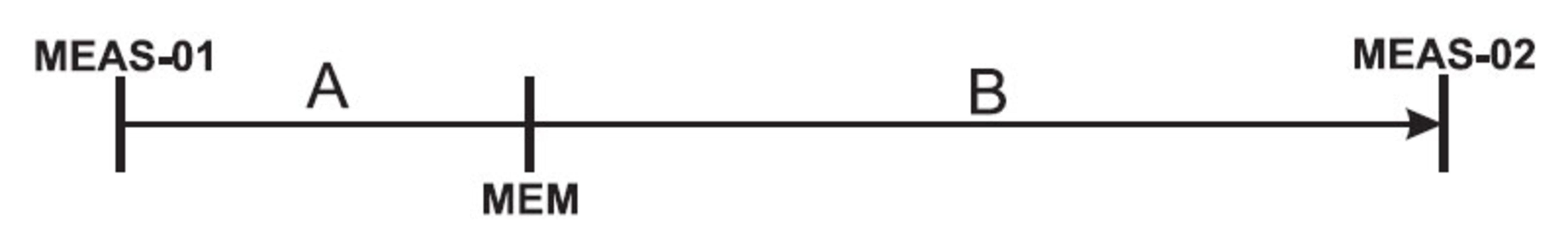
MEAS-01: MEASURE button is pressed (measurement session begins)
A: No logging during this period
MEM: MEM button is pressed momentarily, initial reading is logged and MIN/MAX/AVG logging begins
B: MAX/MIN/AVG readings are tracked and recorded during this period
MEAS-02: MEASURE button is released (measurement session and logging ends)
1. Press and hold the MEASURE button to begin a measurement session as described earlier.
2. While holding down the MEASURE button, press the MEM button momentarily. The reading on the display at the time of the MEM button press (initial reading) will be stored in the current reading set and the MIN/MAX/AVG tracking will begin. Note the reading set memory location on the lower right hand corner of the LCD.
3. The MIN/MAX/AVG readings are calculated over the course of the measurement session (starting from when the MEM button is pressed and ending when the MEASURE button is released). MIN/MAX/AVG readings are stored in the same reading set as the `initial reading’.
4. Release the MEASURE button to end the measurement session.
5. Now, momentary presses of the MEM button step through the initial reading, MAX, MIN, and AVG readings stored in the current memory location. Note that subsequent presses of the MEM button step through the remaining nine memory locations; be sure to note the memory location number when reviewing data to avoid confusion.
6. When recalling data, press and hold the MEM button to quickly jump from one reading set to another. The reading set number, on the lower right, scrolls while the MEM button is held.
Datalogging more than one Reading Set per Measurement Session
If the MEM button is pressed more than once during a measurement session, more than one reading set will be created for that measurement session (one reading set for each MEM press). This is useful if more than one `initial reading’ is desired for a given measurement session. The MIN/MAX/AVG values logged in each reading set represent the MIN/MAX/AVG values recorded between the MEM presses. See the time-line example below:
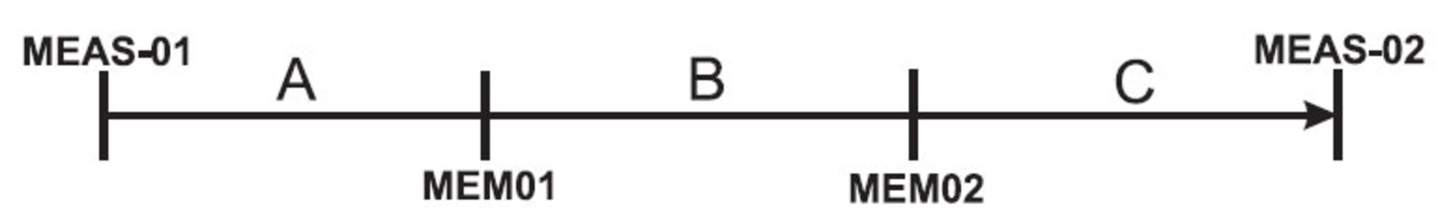
MEAS-01: MEASURE button is pressed (measurement session begins)
A: No logging during this period
MEM01: MEM button is pressed momentarily, logging begins into location `Data 0′
B: Reading set `Data 0′ logs initial reading and MAX/MIN/AVG readings
MEM02: MEM pressed again, previous log (data 0) ends and new log (data 1) begins
C: Reading set `Data 1′ logs initial reading and MAX/MIN/AVG readings for this time period
MEAS-02: MEASURE button is released (measurement session and logging ends)
Reliability / Preventative Maint / Rotational/Tachometers Template | |
|---|---|
| Detection Type | Contact, Non-Contact Laser |
| Display (Tachometer) | LCD |
| Style of Tachometer | Handheld |
| Max Working Distance for Non-Contact | 1.6 Ft |
| Max RPM | 99999 RPM |
| Min RPM | 2 RPM |
| Measurement Modes | Average, Maximum, Minimum |
| Accuracy for Tachmometers | 0.05% rdg +1 digit |
| Memory(Tachometers) | Yes |
Product General Attributes | |
| Warranty | 1 YEARS |
| Safety Approval | CE |
| Product Height | 3.75 IN |
| Product Length | 10.00 IN |
| Product Width | 5.95 IN |
| Data Logging | Yes |
| HTS/Schedule B Number | 9029.20.4080 |
| ECCN Number | EAR99 |
| Calibration Included | Factory Calibration |
| Battery Type | 9v |
| Power Supply Voltage | Battery Powered |
| Country of Origin | China |
| Shipping Height | 3.75 IN |
| Shipping Length | 10.00 IN |
| Shipping Width | 5.95 IN |
You must be logged in to post a review.
| Dimensions | 10 × 5.95 × 3.75 in |
|---|
Related products
Sale

Shimpo DT-2100 – Data-Logging, Contact, Non-Contact Laser Tachometer with USB Output, 6” cir. wheel
Original price was: $379.50.$341.55Current price is: $341.55. Add to cart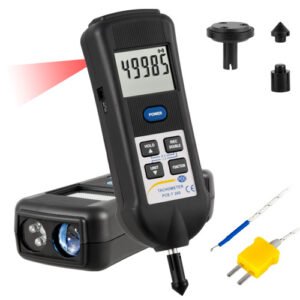
Sale

SKF TKRT 10 Digital Tachometer 5-Digit LCD Backlit Display
Original price was: $617.10.$313.30Current price is: $313.30. Add to cartSale

Testo 460 – Non Contact Tachometer (Part Number 0560 0460)
Original price was: $264.00.$224.40Current price is: $224.40. Add to cart
 Extech RPM33 – Combinati...
 $271.02
Our team of knowledgeable professionals is here to help you make informed decisions. Whether you need product recommendations, technical support, or guidance on your purchase, we're just a click away.
Contact Us Now:
📧 sales@nestesinstruments.com
📞 +1 (833) 763-7837
Let us assist you in finding the perfect solution!
Contact Us Now:
📧 sales@nestesinstruments.com
📞 +1 (833) 763-7837
Let us assist you in finding the perfect solution!
Reviews
There are no reviews yet.