No products in the cart.


Description
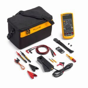
Fluke 287/FVF
- Package with Fluke 287 multimeter, FlukeView Forms software and more
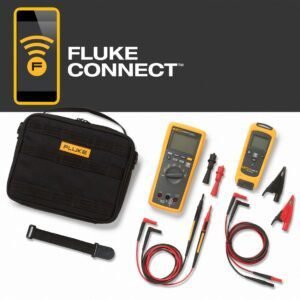
- Does not include Fluke IR3000FC infrared connector for Fluke Connect
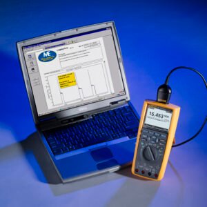
- FlukeView Forms enables you to document, store, and analyze individual readings or series of measurements
- Provides a practical and affordable approach to documenting circuit design performance
FlukeView Forms Combo Kit with 287 Logging Multimeter
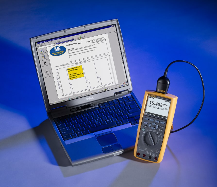
Maximize productivity with the combined Fluke 287 and FlukeView forms combo kit. Designed for today’s professionals involved in R&D, maintenance, manufacture and design of electronic circuits or systems. With built-in data logger and TrendCapture (the meters on screen graphical display) capability, the 287 helps you track down elusive, intermittent problems or monitor equipment with any of its functions.
FlukeView Forms enables you to document, store, and analyze individual readings or series of measurements, overlay logged data to find cause and effect relationships, or turn your data into meaningful graphs and tables for a professional report. The 287 is compatible with the new Fluke ir3000 FC Infrared Connector, allowing you to share live measurements on your iOS or Android smart device with the Fluke Connect mobile app. The 287/FVF combo kit gives you a practical and affordable approach to documenting circuit design performance.
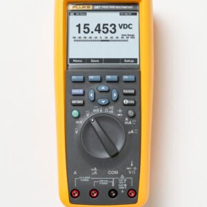
The Fluke 287 True-rms Electronics Logging Multimeter with TrendCapture quickly documents design performance and graphically displays what happened. Its unique logging and graphing capabilities mean you no longer need to download logged readings to a PC to detect a trend. The Fluke 287 packs more accuracy and convenience into a handheld multimeter than ever before.
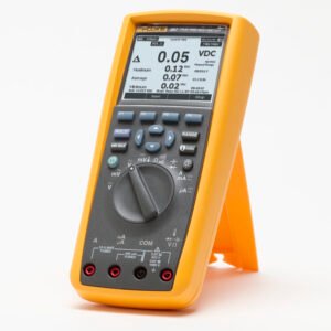
Logging Function with TrendCapture
Logging Function with TrendCapture is an essential tool for documenting the performance of your designs, processes or systems, monitoring unattended while you work on other projects. It plots measurements as a single line to help detect signal anomalies over time, storing up to 10,000 readings. Using on-board TrendCapture, you can graphically view logged readings without a PC. (Software and interface cable not included in all packages)


“i” button on board help screens
“i” button gives you instant access to on-board help screens for every measurement function. Unsure about a function? Select it and Press the “i” button for more information.
MIN / MAX recording mode
The MIN MAX Record mode captures minimum, average, and maximum input values. When the input goes below the recorded minimum value or above the recorded maximum value, the meter beeps and records the new value. The meter stores the elapsed time since the recording session was started at the same time. The MIN MAX mode also calculates an average of all readings taken since the MIN MAX mode was activated.
This mode is for capturing intermittent readings, recording minimum and maximum readings unattended, or recording readings while equipment operation precludes watching the meter. The MIN MAX mode is best for recording power supply surges, inrush currents, and finding intermittent failures.


Capturing peak values
Peak record is very similar to the MIX MAX function, with a signification difference being the shorter response time for peak recording: 250 μs. With this short response time, the actual peak values of a sinusoidal signal are measurable. Transients are more accurately measured using the peak record feature.
In the secondary area of the display, the maximum and minimum peak values as well as the average value are shown along with their respective time stamps. The time stamp next to the average value indicates the elapsed time of the peak recording session. The peak recording session start time is shown along the bottom of the page area of the display.
When the peak value of the input signal goes below the recorded minimum value or above the recorded maximum value, the Meter beeps and records the new value. At the same time, the elapsed time since the peak recording session was started is stored as the recorded value’s time stamp.
Making dB measurements
The Meter is capable of displaying voltage as a dB value, either relative to 1 milliwatt (dBm), a reference voltage of 1 volt (dBV) or a user-selectable reference value.

Screen layout

1. Softkey labels – Indicates the function of the button just below the displayed label
2. Bar graph – Analog display of the input signal
3. Relative – Indicates the displayed value is relative to a reference value
4. Minus sign – Indicates a negative reading
5. Lightning bolt – Indicates hazardous voltage present at the Meter’s input
6. Remote communication – Indicates activity over the communication link
7. Battery level – Indicates the charge level of the six AA batteries
8. Time – Indicates the time set in the internal clock
9. Mode annunciators – Indicates the meter’s mode
10. Mini measurement – Displays the lightning bolt (when necessary) and the input value when the primary and secondary displays are covered by a menu or pop-up message
11. Date – Indicates the date set in the internal clock
12. Beeper – Indicates the meter’s beeper is enabled (not associated with continuity)
13. Units – Indicates the units of measure
14. Auxiliary units – Indicates unitless measurements such as Crest Factor
15. Range indicator – Indicates the range the Meter is in and the ranging mode (auto or manual)
16. Secondary display – Displays secondary measurement information about the input signal
287 and 289 comparison
The chart below outlines main features and differences between the Fluke 287 and 289.
| Features | 287 | 289 |
| Multiple on screen displays | ✔ | ✔ |
| True RMS AC bandwidth | 100 kHz | 100 kHz |
| dBV/dBm | ✔ | ✔ |
| DC mV resolution | 1µV | 1µV |
| Megohm range up to | 500MΩ | 500MΩ |
| Conductance | 50.00nS | 50.00nS |
| Continuity beeper | ✔ | ✔ |
| Elapsed time / time of day clock | ✔ | ✔ |
| Min/max/avg/duty cycle/pulse width | ✔ | ✔ |
| Isolated optical interface for PC connection | ✔ | ✔ |
| Auto/touch hold | ✔ | ✔ |
| 200 hours logging capacity | ✔ | ✔ |
| Low ohm capability | ✔ | |
| LoZ volts | ✔ | |
| Low pass filter | ✔ |

Multimeters Template | |
|---|---|
| Style | Hand-Held |
| Measures AC V | Yes |
| Measures DC V | Yes |
| Measures AC A | Yes |
| Measures DC A | Yes |
| True RMS | Yes |
| Maximum Voltage AC | 1000 V |
| Resolution AC Volts | 0.001 mV |
| Maximum Voltage DC | 1000 V |
| Resolution DC Volts | 0.001 mV |
| Maximum Current AC | 10 A |
| Minimum Current AC | 0.01 uA (0.00001 mA) |
| Resolution AC Current | 0.01 A (10 mA) |
| Maximum Current DC | 10 A |
| Minimum Current DC | 0.01 uA (0.00001 mA) |
| Resolution DC Current | 0.01 A (10 mA) |
| Basic Accuracy V DC | .025% |
| # Digit Display | 4.5 |
| Counts | 50000 . |
| Backlight | Yes |
| Manual/Autoranging | Both |
| Decibels | Yes |
| Resistance | Yes |
| Frequency | Yes |
| Capacitance | Yes |
| Temperature | Yes |
| Diode Testing | Yes |
| CAT Rating | IV CAT Rating CAT III 1000 V / CAT IV 600 V |
| CAT Voltage | 1,000 V |
| Intrinsically Safe | No |
| Peak Hold | Yes |
| Overload Protector | Yes |
| Kelvin 4-Wire Measurement Capability | No |
| Wireless Display | No |
| Data Hold | Yes |
| Low-Pass Filter | Yes |
Product General Attributes | |
| Unique Features | Logging function with TrendCapture. Log data continuously for over 200 hours storing up to 10,000 readings. Low impedance voltage function prevents false readings due to “ghost voltage.” Low Pass Filter for accurate voltage and frequency measurements on adjustable speed motor drives. |
| Warranty | 10 YEARS |
| Warranty Details | Limited lifetime warranty |
| Safety Approval | CSA |
| Interfaces I/O | IR |
| Product Weight | 28 OUNCES (1.75 LBS) |
| Product Height | 2.38 IN |
| Product Length | 8.75 IN |
| Product Width | 4.03 IN |
| Data Logging | Yes |
| Calibration Included | Factory Calibration |
| Power Supply Voltage | Battery Powered |
| Country of Origin | United States |
| Shipping Height | 3.75 IN |
| Shipping Length | 12.25 IN |
| Shipping Width | 10.75 IN |
You must be logged in to post a review.
Manuals/Guides
BrochuresManualsOther
| Weight | 28 lbs |
|---|---|
| Dimensions | 8.75 × 4.03 × 2.38 in |
Related products
Sale

Fluke 179/EDA2 KIT – True RMS Digital Multimeter for Troubleshooting/Repair with EDA2 Accessory Kit
Original price was: $549.98.$467.81Current price is: $467.81. Add to cartSale

Fluke 87V/E2 – Industrial Electrician Combo Kit with 87-5 Multimeter and Additional Accessories
Original price was: $824.98.$699.54Current price is: $699.54. Add to cartSale
Fluke 88-5/A KIT – Automotive Multimeter Combo Kit
Original price was: $844.99.$679.96Current price is: $679.96. Add to cartSale

Fluke 87V/IMSK – Industrial Multimeter Service Combo Kit with 87-5 and i400 AC Current Clamp
Original price was: $648.98.$552.02Current price is: $552.02. Add to cartSale
Fluke V3000 FC Kit FC Wireless Essential KIT With V3000
Original price was: $637.98.$542.67Current price is: $542.67. Add to cart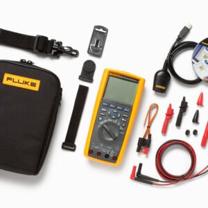 Fluke 287/FVF – FlukeVie...
 $1,110.98
Our team of knowledgeable professionals is here to help you make informed decisions. Whether you need product recommendations, technical support, or guidance on your purchase, we're just a click away.
Contact Us Now:
📧 sales@nestesinstruments.com
📞 +1 (833) 763-7837
Let us assist you in finding the perfect solution!
Contact Us Now:
📧 sales@nestesinstruments.com
📞 +1 (833) 763-7837
Let us assist you in finding the perfect solution!
Reviews
There are no reviews yet.