No products in the cart.
Sale

Description

Jenway 451200
- Automatic selection of range for best resolution
- Simultaneous display of conductivity or TDS and temperature
- Automatic standard recognition
- Calibration by cell constant or standard solutions
- Storage of up to 32 results
4510 Bench Conductivity/TDS Meter
4510 conductivity meter supplied with glass conductivity probe with ATC (K= 1) (027 013), electrode holder, 230v
The 4510 is easy to use but with the flexibility to meet the broadest range of applications and for those where greater accuracy is required the 4510 has automatic conductivity standard recognition and endpoint detection. Set-up options include cell constant, temperature coefficient and reference temperature. The instrument can store up to 32 readings, which can also be sent to a printer or transferred to computer via DataWay and the RS232 interface.

Display
1. Standard selection – indicates which type of standard is being used. Also indicates when a calibration is being performed.
2. Symbol – displayed during set-up of instrument parameters.
3. Primary display – 4½ digit. Provides direct readout in Conductivity or TDS of samples and standards.
4. Mode annunciators – shows selected measurement mode; Conductivity (µS or mS) and TDS (mg/l or g/l).
5. Endpoint symbol
6. Secondary display – 6 digit display. Provides direct readout of automatic or manual temperature. Scrolls and displays selected parameter information in set-up mode.
7. Status display – 2½ digit.
8. Mode annunciators – indicates temperature in °C or °F and whether the measurements are manually or automatically temperature compensated.
9. Mode tags – Each mode tag is highlighted when selected; SETUP, MODE or RESULTS.
Keypad
1. ESC used to switch the instrument on and to place into standby mode (only if power supply lead remains connected to the instrument). Also used to escape/exit a mode.
2. CAL / CLR used to select and perform a calibration sequence. This key is also used to clear readings from Memory. Used to select Abs/Rel mV in mV mode.
3. Print key used to initiate a print.
4. Up Arrow used for adjustment during set up, to scroll results and to toggle between mV and pH modes.
5. Down Arrow used for adjustment during set up, to scroll results and to toggle between mV and pH modes.
6. Left Arrow used for adjustment during set up and to move between mode tags.
7. Right Arrow used for adjustment during set up and to move between mode tags.
8. STO used to accept an entered value in set-up mode and to instigate a stored reading. This key can also be used as a CAL key during calibration.


Rear panel layout
1. Conductivity Socket 7 pin DIN socket which allows the conductivity cell to be connected.
2. Analog Out 2 x 4mm sockets. Analogue output (buffered electrode potential).
3. Output Socket 9 way socket for RS232 connection.
4. Power In AC 9V I/P socket. 2.1 x 5.5mm socket allowing the power supply to be connected to the instrument.
Product General Attributes | |
|---|---|
| Warranty | 3 YEARS |
| Interfaces I/O | RS-232 |
You must be logged in to post a review.
Manuals/Guides
ManualsSpec Sheets
Related products
Sale

Testo 410-2 – Vane Anemometer with Humidity Measurement (Part number 0560 4102)
Original price was: $291.50.$247.77Current price is: $247.77. Add to cartSale
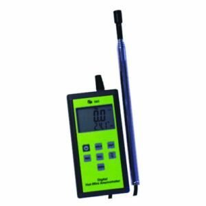
TPI 565C1 Digital Hot Wire Anemometer
Original price was: $186.94.$171.98Current price is: $171.98. Add to cartSale
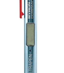
Myron PT2 Myron L UltraPen – pH & Temperature
Original price was: $284.90.$236.01Current price is: $236.01. Add to cartSale

TSI 9545 VelociCalc Air Velocity Meter with Straight Probe
Original price was: $1,837.00.$1,653.30Current price is: $1,653.30. Add to cartSale
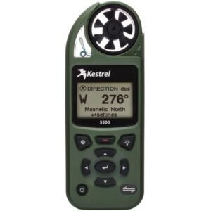
Kestrel 0855LVOLV – 5500 Pocket Weather Meter with Link and Vane Mount (Olive)
Original price was: $589.60.$471.90Current price is: $471.90. Add to cart Jenway 451200 – 4510 Ben...
 Original price was: $787.60.$771.84Current price is: $771.84.
Our team of knowledgeable professionals is here to help you make informed decisions. Whether you need product recommendations, technical support, or guidance on your purchase, we're just a click away.
Contact Us Now:
📧 sales@nestesinstruments.com
📞 +1 (833) 763-7837
Let us assist you in finding the perfect solution!
Contact Us Now:
📧 sales@nestesinstruments.com
📞 +1 (833) 763-7837
Let us assist you in finding the perfect solution!
Reviews
There are no reviews yet.