No products in the cart.


Description
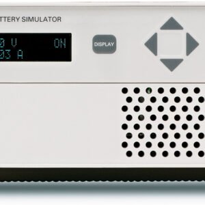
Keithley 2302 – Battery Simulator, 15V, 5A

- Number of Outputs: 1
- Maximum Voltage: 15V
- Maximum Current: 5A
- Connectivity: GPIB
The single-channel Model 2302 Battery Simulator is designed specifically for development and test applications of portable, battery-operated products, such as cellular and cordless telephones, mobile radios, and pagers. These precision power supplies have ultrafast transient response so they can have output characteristics identical to actual batteries. These supplies employ a unique variable output resistance so the voltage output can emulate a battery’s response (U.S. Patent No. 6,204,647). They provide stable voltage outputs, even when a device-under-test (DUT) makes the rapid transition from the standby (low current) state to the RF transmission (high current) state. In addition, they can monitor DUT power consumption by measuring both DC currents and pulse load currents. The Model 2302’s and the Model 2302’s battery-simulator channel can be programmed to operate like a discharged rechargeable battery, sinking current from a separate charger or from the Model 2302’s charger-simulator channel.
Maximize Test Throughput with Accurate Battery Simulation
The battery-output channels of the Models 2302 is designed to simulate the output response of a battery. This capability, combined with their fast transient response, makes it possible to power the device during testing in exactly the same way as a battery will power the device during actual use. The output resistance of the Model 2302 battery channel can be programmed (with 10mW resolution) over the range from 0W to 1W so that the output resistance can be set to the same level as the output resistance of the battery that powers the device. See Figure 1.

Figure 1. Simplified schematic of a battery and the 2302
Portable wireless devices make great demands on their battery power sources. The battery must source load currents that can jump virtually instantaneously from a standby current level (100–300mA) to a full-power RF transmission current level (1–3A). In other words, the load current on the battery can increase rapidly by a factor of 700–1000%. As a result, the battery voltage drops by an amount equal to the value of the current change multiplied by the battery’s internal resistance. The Models 2302 power supplies enable test systems to duplicate this voltage drop by programming their output resistance to be equivalent to that of the battery that will power the device. This allows wireless device manufacturers to test their products under the same power conditions that they will encounter in actual use. (See Figure 2.)

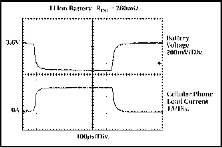
Figure 2. Comparison of the voltage outputs of a lithium-ion battery (with an internal resistance of 260mW) (programmed with an output resistance of 260mW) when powering a cellular telephone as it makes the transition from standby mode to transmit mode.
In response to large load changes, the Model 2302 have transient voltage droops of less than 100mV and transient recovery times of less than 60μs, even when the test leads between the power supply and the DUT are long. This fast transient response, combined with the supplies’ variable output resistance, allows engineers to test their portable products under the most realistic operating conditions and eliminate false failures due to conventional power supplies with slow response times. (See the sidebar titled “Conventional Power Supplies and Wireless Device Testing.”) These supplies also eliminate the large stabilizing capacitors needed at the DUT to compensate for the large droop that occurs when testing with conventional power supplies. By varying the output resistance, which can be done while the output is turned on, test engineers can simulate the operation of different battery types, as well as batteries nearing the end of their useful lives.
The Models 2302 ensure maximum production throughput when testing portable devices by minimizing false failures, minimizing the number of test setups by performing multiple tests with the same power supply, and minimizing test fixture complexity by eliminating the need for voltage- stabilizing capacitors.
Measure Load Currents for Power Consumption Verification or Analysis
As manufacturers of portable devices strive to extend their products’ battery life, measuring load currents accurately has become increasingly essential in both design and production test in order to ensure the product meets its demanding specifications. Comprehensive testing of these devices requires measuring peak currents, average currents, and baseline currents in various operation modes. When testing these devices, these measurements are complicated by the pulsating nature of load currents, such as the transmit and receive load currents of digital cellular phones. The Models 2302 can measure the peak and average currents of pulses as short as 60μs and as long as 833ms. (See Figure 3.)

Figure 3. Built-in pulse current measurement functions allow test engineers to measure peak, average, and baseline load currents.
Measure Long-Period Waveform Currents
For pulse trains with periods longer than 850ms, the Models 2302 offer a unique, long integration current measurement mode. This mode can provide an average measurement of a current waveform from 850ms up to 60 seconds long.
Measure Low Currents Accurately
The Models 2302 is based on Keithley’s expertise in low current measurement technologies, so they’re well-suited for making fast, accurate measurements of sleep and standby mode currents. With 100nA resolution and 0.2% basic accuracy, they provide the precision needed to monitor the low sleep mode currents of both today’s battery-operated products and tomorrow’s.
Verify Load Currents in All Operating States
The Models 2302 employ a unique pulse current step function for measuring the load current at each level of a device’s operational states. (See Figure 4.) For example, if a cellular phone is ramped up and down through as many as 20 discrete power consumption states, the Models 2302 can measure the load currents in synchronization with the current steps. This capability allows a test engineer to verify performance at each operational state and simultaneously acquire power consumption information. The fast current measure capability is another way the Models 2302 power supplies save test time and production costs.

Figure 4. These power supplies can obtain a load current profile synchronized to the transitions of a DUT as it is stepped through its operating states.
Simulate a Discharged Battery for Charger Testing
The Models 2302 can sink up to 3A continuously, just like an electronic load. This allows these supplies to simulate a discharged rechargeable battery for use in testing the performance of battery chargers or battery charger control circuitry.
Open-Sense Lead Detection
The Model 2302 have an automatic open–sense lead detection capability, which indicates if there is a broken remote sense lead or an open connection from a remote sense lead to the test fixture.

Figure 5. For charger control circuit testing applications, the Model 2302 can provide the functions of both a chargersimulating source and a discharged battery simulator.
the output voltage does not change from the programmed level, which could cause production devices to be improperly calibrated, the user can set high and low limits around the desired voltage level.
Independent Digital Voltmeter Inputs
Many programmable power supplies offer output readback capabilities, but the Model 2302 also offer DVM inputs. Both instruments allow measuring signals from –5V to +30V DC anywhere in the test system with the same rated accuracy as the voltage readback. The Model 2302 has one. The DVMs and the power sources can operate simultaneously. For many applications, these built-in DVMs eliminate the expense and space required to add a separate voltage measurement instrument.

Figure 6. Model 2302 Battery Channel Block Diagram. The Model 2302 charger channel is identical except it does not have the variable output resistance.
Big Functionality in a Small Package
For high volume production environments where floor and test rack space are at a premium, In addition to power control, both the Model 2302 provide extensive measurement capabilities in the same halfrack case. The front panel of each unit displays the user’s choice of either the output voltage and output current, the average, peak, and baseline pulse current levels, long integration currents, or DC DVM measurements. A minimum of front panel buttons ensures that operation is simple and straightforward.
For additional control requirements, the Models 2302 have four digital relay control outputs and a 5V DC output to power a relay coil.

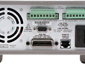
Figure 7. Model 2302 Rear Panel showing 8-position power output connectors, RJ-45 remote display connector, DB-9 relay output connector, IEEE-488 connector, and power input socket.
Power Supplies/DC Power Supplies Template | |
|---|---|
| Outputs | Single |
| Voltage Output 1 | Variable |
| Max Voltage Output 1 | 15 V |
| Programmable | Yes |
| Current Output 1 | Variable |
| Max Current Output 1 | 5 A |
| Meter Type | Digital |
| Max Display Resolution Current | 0.1 uA (0.00010 mA) Max Display Resolution Current 5m A Range |
| Max Display Resolution Voltage | 1 mV |
| Constant current/voltage | Yes |
| Remote Sensing | Yes |
Product General Attributes | |
| Warranty | 1 YEARS |
| Safety Approval | CE |
| Interfaces I/O | GPIB |
| Power Supply Voltage | 120V 50/60 Hz |
| Country of Origin | China |
You must be logged in to post a review.
Manuals/Guides
BrochuresManualsSpec SheetsApplication Notes
Related products


 Keithley 2302 – Battery ...
 $4,994.00
Our team of knowledgeable professionals is here to help you make informed decisions. Whether you need product recommendations, technical support, or guidance on your purchase, we're just a click away.
Contact Us Now:
📧 sales@nestesinstruments.com
📞 +1 (833) 763-7837
Let us assist you in finding the perfect solution!
Contact Us Now:
📧 sales@nestesinstruments.com
📞 +1 (833) 763-7837
Let us assist you in finding the perfect solution!
Reviews
There are no reviews yet.