No products in the cart.


Description

Keysight 34980A/001
- THIS MODEL DOES NOT HAVE AN INTERNAL DMM (OPTION 001)
- Flexible, reliable switching and data acquisition platform
- Mainframe only
- Modules sold separately – over 20 models available
- Eight module slots on rear of mainframe
Multifunction Switch / Measure Unit Mainframe (without Internal DMM)
The 34980A multifunction switch/measure unit provides functionality that is easy to set up and use with a fast startup time. The 34980A helps you lower your test cost and accelerate your test-system integration and development.
The 34980A handles system switching up to 26.5 GHz and provides basic measurements and system control. It also offers DMM measurements, counter/ totalizer functionality, digital I/O with pattern capabilities, and analog outputs with basic waveforms – all in one low-cost, compact box. And with its standard connectors and software drivers, computer-standard I/O, and Web browser interface, the 34980A easily integrates into electronic functional test and data acquisition systems.
Information on modules (sold separately)
The Keysight 34980A/001 is a 34980A with option 001. Option 001 removes the 6.5 digit internal DMM.
The 34980A accommodates up to 8 plug-in modules to give you the flexibility you need. Choose from over 20 different modules to define your own configuration. You can buy what you need now and add to it or reconfigure it as your requirements change.
Whether you are measuring temperature, AC or DC voltage, resistance, frequency, current, or custom measurements, the 34980A offers the functionality you need in a single box. Switch in different measurements with high-performance signal switching up to 300V with no external signal conditioning required. Choose between different switch types and topologies with frequency ranges from DC to 26.5 GHz. The 34980A offers high-density multiplexers for scanning multiple channels, matrices for connecting multiple points at one time, and general-purpose switches for simple control and high power needs.
The charts below provide a brief overview of module part numbers and specifications. For more detailed information, please view the document linked here beginning on page 9.
Each module type below is also clickable and will open that particular product series in a new window.
Multiplexer modules
| Model | Description | Max voltage | Switch/carry | Scan ch/sec |
| 34921A | 40-channel armature mux w/ low thermal offset | ±300V | 1A/2A | 100 |
| 34922A | 70-channel armature mux | ±300V | 1A/2A | 100 |
| 34923A | 40 / 80-channel reed mux | ±150V | 0.5A/1.5A | 500 |
| 34924A | 70-channel reed mux | ±150V | 0.5A/1.5A | 500 |
| 34925A | 40 / 80-channel optically isolated FET multiplexer | ±80V | 0.002A | 1000 |
Matrix modules
| Model | Description | Max voltage | Switch/carry | Scan ch/sec |
| 34931A | Dual 4×8 armature matrix | ±300V | 1A/2A | 100 |
| 34932A | Dual 4×16 armature matrix | ±300V | 1A/2A | 100 |
| 34933A | Dual/quad 4×8 reed matrix | ±150V | 0.5A/1.5A | 500 |
| 34934A | Quad 4×32 reed matrix | ±100V | 0.5A/1.5A | 500 |
RF and microwave modules
| Model | Description | Insertion Loss | Isolation | Freq Range |
| 34941A | Quad 1×4 50 ohm 3 GHz RF multiplexer | 0.6dB | >58dB | 3 GHz |
| 34942A | Quad 1×4 75 ohm 1.5 GHz RF multiplexer | 0.6dB | >60dB | 1.5 GHz |
| 34945A/EXT | Microwave switch/attenuator driver | |||
| 34946A | Dual 1×2 SPDT terminated microwave switch 4 GHz, 20 GHz, or 26.5 GHz | <0.42dB <0.69dB <0.8dB | >85dB >67dB <60dB | <1.15 <1.30 <1.6 |
| 34947A | Triple 1×2 SPDT unterminated microwave switch 4 GHz, 20 GHz, or 26.5 GHz | <0.42dB <0.69dB <0.8dB | >85dB >67dB <60dB | <1.15 <1.30 <1.6 |
System control modules
| Model | Description | Function |
| 34950A | 64-bit digital I/O with memory and counter | Eight 8-bit digital I/O channels with programmable polarity, handshaking protocols, and pattern memory |
| 34951A | 4-channel isolated D/A converter with waveform memory | C voltage up to ±16V or DC current up to ±20mA. 16 bits waveforms with a 200 kHz update rate |
| 34952A | Multifunction module with 32-bit DIO, 2-ch D/A and totalizer | Four 8-bit digital I/O channels, two ±12-V analog outputs, and a 100 kHz gated totalizer |
| 34959A | Breadboard module | Create your own custom designs with +12V and +5V supplies, 16 GPIO, and 28 relay drive lines |
General purpose / actuator switch modules
| Model | Description | Max voltage | Switch/carry | Scan ch/sec |
| 34937A | 28-channel Form C and 4-channel Form A | ±300V/±250VAC | 1A/2A/5A | N/A |
| 34938A | 20-channel 5-amp Form A | ±250VAC | 5A/8A | N/A |
| 34939A | 64-channels Form A | ±100VAC | 1A/2A | N/A |
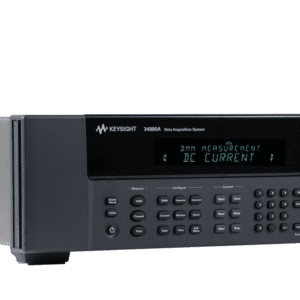
Front panel

1. The On/Standby switch is used to toggle the 34980A between On and Standby modes only. To turn the unit off, remove the power cord.
2. The Utility key accesses menus to configure Remote I/O (LAN, GPIB, and USB) operation, set Date and Time, and configure other system-related instrument parameters.
3. The Store/Recall key allows you to save and recall up to six instrument setups.
4. Control keys directly control module actions.
5. The number keypad is used for entering numerical characters.
6. The exponent entry key is used to enter the exponent during a numerical entry.
7. The Cancel key exits any menu without saving changes.
8. Arrow keys move the cursor position in an entry.
9. The knob provides for entry of alphanumeric characters, selecting slots or channels, and navigating menus.
10. The Enter key steps you through a menu or saves number entries.
11. Running a program puts the display into “remote” and disables the front panel keys. Local takes you out of “remote” mode and enables the front panel keys.
12. Configure keys select functions and set function parameters.
13. Measure keys execute and monitor measurements. Depending on which measurement key you use, you can have complete/direct control over the switching and measurement operation, or you can have the 34980A automatically control these to capture the desired data.
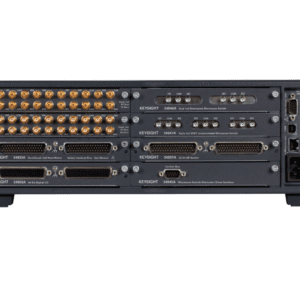
Rear panel

1. Access to Analog Buses (shown with removable cover installed)
2. Module installed in slot 1 (for illustrative purposes – modules sold separately)
3. Slot identifier
4. Module ground screw
5. Slot cover over slot 2
6. AC power connector
7. LAN connector (10Base T/100Base Tx)
8. USB 2.0 connector
9. External trigger input
10. Internal DMM option mark. If ordered with internal DMM option, the circle is marked black
11. IEEE 488.2 GPIB Connector
12. Chassis ground screw
You must be logged in to post a review.
Manuals/Guides
BrochuresManualsSpec Sheets
Related products


Sale

CPS TS-100-6PK – Temperature & Humidity Data Logger 6 Pack
Original price was: $373.28.$323.51Current price is: $323.51. Add to cartSale

Digi-Sense 18004-13 – TraceableGO Temperature and Humidity Data Logger
Original price was: $85.80.$71.50Current price is: $71.50. Add to cartSale

Digi-Sense 18000-31 – Ambient CO2/Temperature/Humidity Data Logger with TraceableLIVE® Wireless Capability and Calibration
Original price was: $814.00.$678.33Current price is: $678.33. Add to cart Keysight 34980A/001 – Mu...
 $4,182.20
Our team of knowledgeable professionals is here to help you make informed decisions. Whether you need product recommendations, technical support, or guidance on your purchase, we're just a click away.
Contact Us Now:
📧 sales@nestesinstruments.com
📞 +1 (833) 763-7837
Let us assist you in finding the perfect solution!
Contact Us Now:
📧 sales@nestesinstruments.com
📞 +1 (833) 763-7837
Let us assist you in finding the perfect solution!
Reviews
There are no reviews yet.