No products in the cart.


Description
Pico 3206D MSO – PicoScope 200 MHz 2-Channel Mixed-Signal Oscilloscope
- 16 digital channels
- Automatic measurements
- Mask limit testing
- Advanced triggers
- Serial decoding
- Math channels
- Spectrum analyzer
- Free technical support and updates
- Free SDK and example programs
- 5 year warranty included
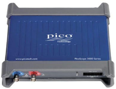
The PicoScope 3000 Series
Power, portability, and performance
The PicoScope 3000 Series PC oscilloscopes are small, light, and portable, while offering the high-performance specifications required by engineers in the lab or on the move.
These oscilloscopes offer 2 or 4 analog channels, plus an additional 16 digital channels on the MSO models. The flexible, high-resolution display options enable you to view and analyze each signal in fine detail.
Operating together with the PicoScope 6 software, these devices offer an ideal, cost-effective package for many applications, including embedded systems design, research, test, education, service, and repair.
High-end features as standard
Buying a PicoScope is not like making a purchase from other manufacturers, where optional extras considerably increase the price. With our scopes, high-end features such as resolution enhancement, mask limit testing, serial decoding, advanced triggering, a spectrum analyzer, math channels, XY mode, segmented memory, a function generator, and an arbitrary waveform generator are all included in the price.
To protect your investment, both the PC software and the firmware inside the scope can be updated. Pico Technology have a long history of providing new features through free-of-charge software downloads. Users of our products reward us by becoming lifelong customers and frequently recommending PicoScopes to their colleagues.

High bandwidth and sampling rate
Despite their compact size and low cost, there is no compromise on performance. With input bandwidths up to 200 MHz, the PicoScope 3000 Series scopes can measure a wide range of signal types, from DC and baseband into RF and all the way up to VHF.
A real-time sampling rate of 1 GS/s allows detailed display of high frequencies. For repetitive signals, the maximum effective sampling rate can be boosted to 10 GS/s using Equivalent Time Sampling (ETS) mode. With a sampling rate of at least five times the input bandwidth, PicoScope 3000 Series oscilloscopes are well equipped to capture high-frequency signal detail.
Deep memory
PicoScope 3000 Series oscilloscopes offer a huge buffer memory, allowing them to sustain high sampling rates across long timebases. For example, using the 512 MS buffer the PicoScope 3206 and 3406 models can sample at 1 GS/s all the way down to 50 ms/div (500 ms total capture time).
Powerful tools are included to allow you to manage and examine all of this data. As well as functions such as mask limit testing and color persistence mode, the PicoScope 6 software enables you to zoom into your waveform by several million times. The Zoom Overview window allows you to easily control the size and location of the zoom area.
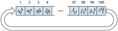
Up to 10 000 waveforms can be stored in the segmented waveform buffer. The Buffer Overview window then allows you to rewind and review the history of your waveform. No longer will you struggle to catch an infrequent glitch.
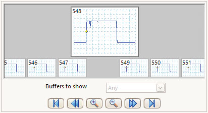
When the trace length is set to be shorter than the scope’s memory, the PicoScope will automatically configure the memory as a circular buffer, recording recent waveforms for review. For example, if 1 million samples are captured, up to 500 waveforms will be stored in oscilloscope memory. Tools such as mask limit testing can then be used to scan through each waveform to identify anomalies.
Advanced display
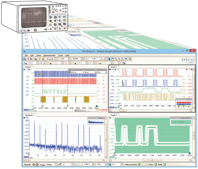
The PicoScope software provides advanced detail and clarity for viewing your signals. The majority of the display area is dedicated to the waveform, ensuring that a huge amount of data can be seen at once. Even with a laptop, the viewing area for a PicoScope USB oscilloscope is far larger than that of a typical benchtop oscilloscope.
- Size
- The size of the display is only limited by the chosen PC. With a large waveform area available, you can select a customizable split-screen display to view multiple channels or different views of a signal at the same time. The software can even show multiple oscilloscope and spectrum analyzer traces at once.
- Flexibility
- Each waveform shown in a customized view works with individual zoom, pan, filter, and measurement tools for ultimate flexibility. The buffer overview function also allows you to quickly find rare, highspeed events in a long capture, ensuring you are always viewing the most relevant data.
- Resolution
- The superior resolution offered by a PC monitor means that even with multiple views or complex signals, no detail will be lost.
- Ease of use
- The PicoScope software controls are easy to access and use within the large display window. You can clearly read all the settings and data for your waveform.
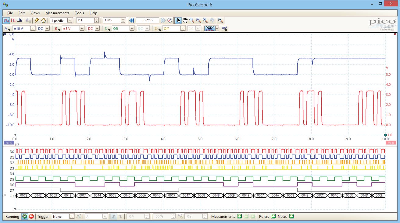
Mixed-signal oscilloscopes
The PicoScope 3000 Series MSO (Mixed-Signal Oscilloscope) models include 16 digital inputs alongside the standard 2 or 4 analog channels, enabling you to view your digital and analog signals simultaneously.
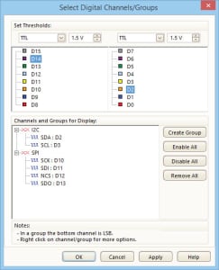
To view the digital signals in the PicoScope 6 software, simply click the digital channels button.
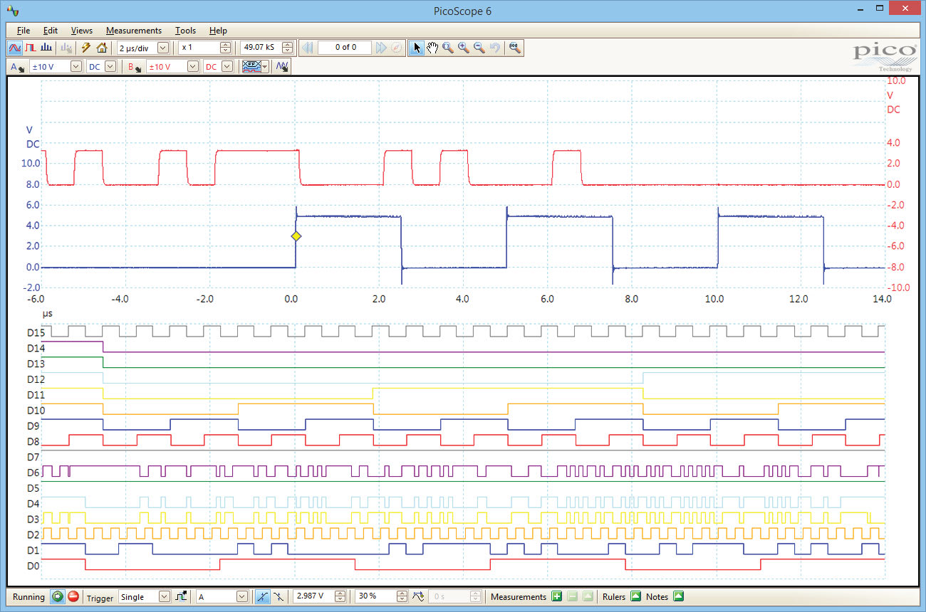
The 16 digital inputs can be added to the view by dragging and dropping, and can then be reordered, grouped, and renamed. The channels can be displayed individually or in arbitrary groups labelled with binary, decimal or hexadecimal values. A separate logic threshold from –5 V to +5 V can be defined for each 8-bit input port. The digital trigger can be activated by any bit pattern combined with an optional transition on any input.
Advanced logic triggers can be set on either the analog or the digital input channels, or both.
Advanced digital triggers
Since 1991 Pico Technology have been pioneering the use of digital triggering and precision hysteresis using the actual digitized data. Traditionally digital oscilloscopes have used an analog trigger architecture based on comparators, which can cause time and amplitude errors that cannot always be calibrated out. Additionally, the use of comparators can often limit the trigger sensitivity at high bandwidths and can create a long trigger rearm delay.
PicoScopes broke new ground by being the first to use digital triggering. This method reduces errors and allows our oscilloscopes to trigger on the smallest signals, even at the full bandwidth. Trigger levels and hysteresis can be set with high precision and resolution.
Digital triggering also reduces rearm delay and this, combined with the segmented memory, allows the triggering and capture of events that happen in rapid sequence. At the fastest timebase you can use rapid triggering to collect 10 000 waveforms in under 6 milliseconds. The mask limit testing function can then scan through these waveforms to highlight any failed waveforms for viewing in the waveform buffer.

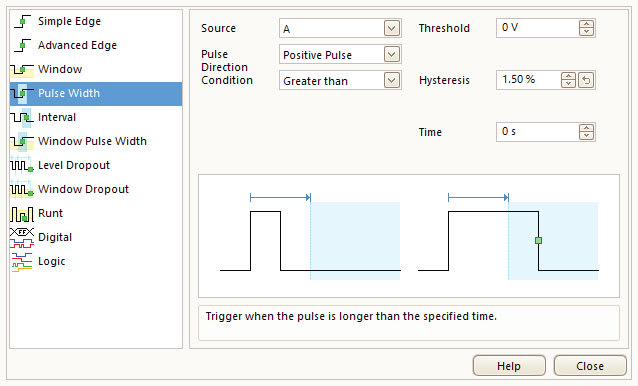
As well as simple edge triggers, a selection of time-based triggers are available for both digital and analog inputs.
- The pulse-width trigger allows you to trigger on either high or low pulses, which are shorter or longer than a specified time, or which fall inside or outside a range of times.
- The interval trigger measures the time between subsequent rising or falling edges. This allows you to trigger if a clock signal falls outside of an acceptable frequency range, for example.
- The dropout trigger fires when a signal stops toggling for a defined interval of time, functioning as a watchdog timer.
Triggering for digital inputs
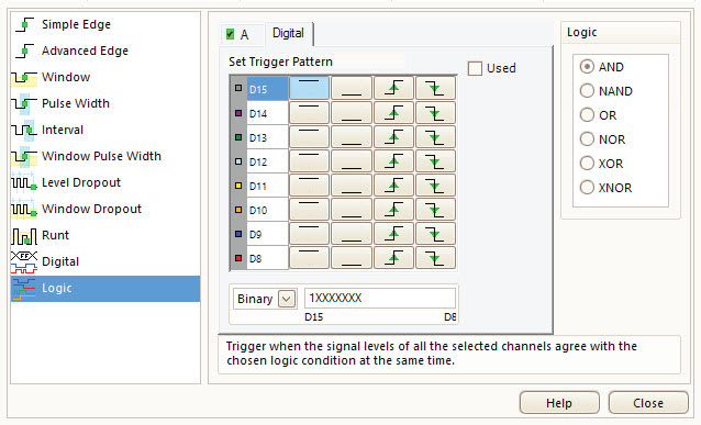
The PicoScope 3000 Series MSO models offer a comprehensive set of advanced triggers for digital channels.
With logic triggering you can trigger the scope when any or all of the 16 digital inputs match a user-defined pattern. You can specify a condition for each channel individually, or set up a pattern for all channels at once using a hexadecimal or binary value. You can also combine logic triggering with an edge trigger on any one of the digital or analog inputs, to trigger on data values in a clocked parallel bus for example.
Serial decoding
Serial protocols: UART/RS-232, SPI, I2C, I2S, CAN, LIN, FlexRay, USB
The deep-memory PicoScope 3000 Series oscilloscopes include serial decoding capability across all channels, and can capture thousands of frames of uninterrupted data, making them ideal devices for the job.
The decoded data can be displayed in the format of your choice: in graph, in table, or both at once.
In graph format shows the decoded data beneath the waveform on a common time axis, with error frames marked in red. These frames can be zoomed to investigate signal integrity (SI) issues.
In table format shows a list of the decoded frames, including the data and all flags and identifiers. You can set up filtering conditions to display only the frames you are interested in, search for frames with specified properties, or define a start pattern to signal when the program should list the data.
PicoScope also includes options to import and export the decoded data using a Microsoft Excel spreadsheet.


Serial decoding for digital signals
The PicoScope 3000 Series MSO models bring extra power to the serial decoding features. You can decode serial data on all analog and digital inputs simultaneously, giving you up to 20 channels of data with any combination of serial protocols. For example, you can decode multiple SPI, I²C, CAN bus, LIN bus and FlexRay signals all at the same time!
Function generator
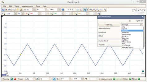
PicoScope 3000 Series oscilloscopes all include both a built-in function generator and an arbitrary waveform generator (AWG), allowing you to create standard and custom-defined waveform outputs.
The function generator includes sine, square, triangle, DC voltage, and a number of other common modes as standard. The capability to generate white noise and pseudo-random binary sequence (PRBS) outputs is also included. In addition to basic controls to set level, offset and frequency, more advanced controls allow you to sweep over a range of frequencies and trigger the generator from a specified event. Combined with the spectrum peak hold option, this becomes a powerful tool for testing amplifier and filter responses.
Arbitrary waveform generator
All PicoScope 3000 Series oscilloscopes also include a built-in arbitrary waveform generator (AWG). With most competing oscilloscopes, you would need to purchase separate hardware to gain this functionality, taking up extra space on your workbench.
The AWG can be used to emulate missing sensor signals during product development, or to stress test a design over the full intended operating range.
Waveforms can be created or modified using the AWG editor, imported from oscilloscope traces, or loaded from a spreadsheet; with the PicoScope’s integrated hardware, these tasks can be performed instantly and easily.

HAL3 hardware acceleration
Many oscilloscopes struggle when deep memory is enabled: the screen update rates can slow and the controls can become unresponsive. The PicoScope 3000D Series oscilloscopes avoid this limitation with the use of a dedicated hardware acceleration engine. This parallel design enables the oscilloscope to intelligently compile the waveform image from the raw data stored in its memory before transferring it to the PC, so that the USB connection and PC’s processor performance do not limit capture rates. This allows the continuous capture and display of over 440 000 000 samples every second. PicoScope oscilloscopes manage deep memory far more effectively than competing PC-based and benchtop models.
The PicoScope 3000D Series is fitted with third-generation hardware acceleration (HAL3), which allows high waveform update rates and faster segmented memory and rapid trigger modes. In most cases the data collection speed of the PicoScope will be faster than the USB transfer rate, so information has to be buffered in high-speed memory on the device. HAL3 allows even deep-memory PicoScopes to maintain fast waveform update rates regardless of the buffer size.
For example, the PicoScope 3206D can sample at 1 GS/s on timebases as long as 20 ms/div, capturing 200 million samples per waveform, and still update the screen several times per second. That’s around 500 million sample points each second!
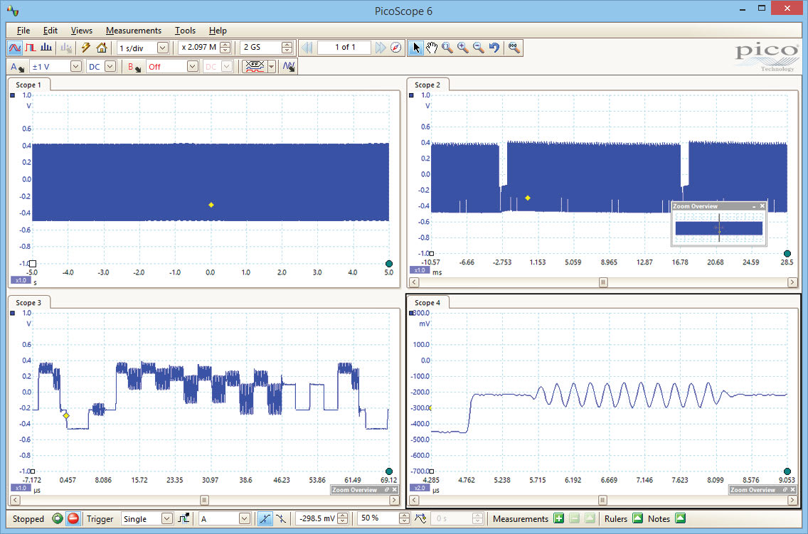
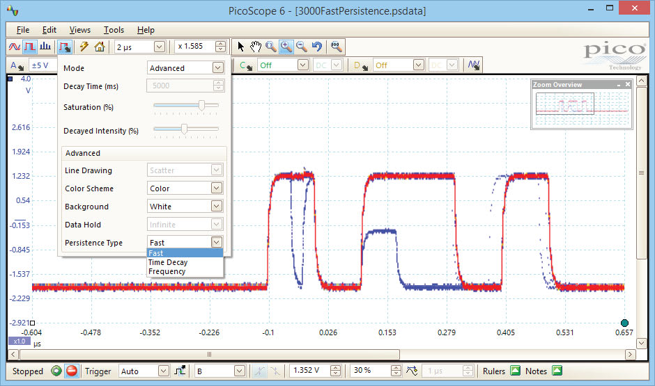
Less intelligent oscilloscopes attempt to reduce the amount of data transferred by using simple decimation, transferring only every nth sample. This results in the majority (up to 99.999%) of data being lost and a lack of high-frequency information. PicoScope deep-memory oscilloscopes perform data aggregation instead. Dedicated logic divides the memory into blocks and transfers the minimum and maximum values of each block to the PC, preserving the high-frequency detail.
For example, a waveform with 100 million samples may be divided into 1000 blocks of 100 000 samples each, with only the minimum and maximum values for each block being transferred to the PC. If you zoom into the waveform, the oscilloscope will again divide the selected area into blocks and transfer the minimum and maximum data so that fine detail is viewable without any delay.
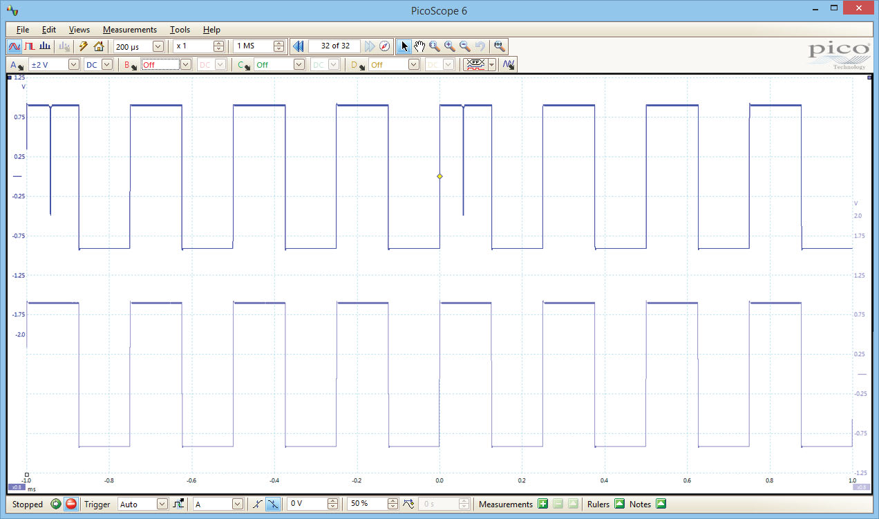
In the example above, both waveforms show the same signal using different types of hardware acceleration. The top waveform has used the aggregation possible with a PicoScope, and as a result the high-frequency spikes are preserved. The bottom waveform has used traditional decimation, showing a loss of high-frequency information.
In parallel with the data aggregation, other data such as average values are also returned to speed up measurements and to reduce the load on the PC’s processor.
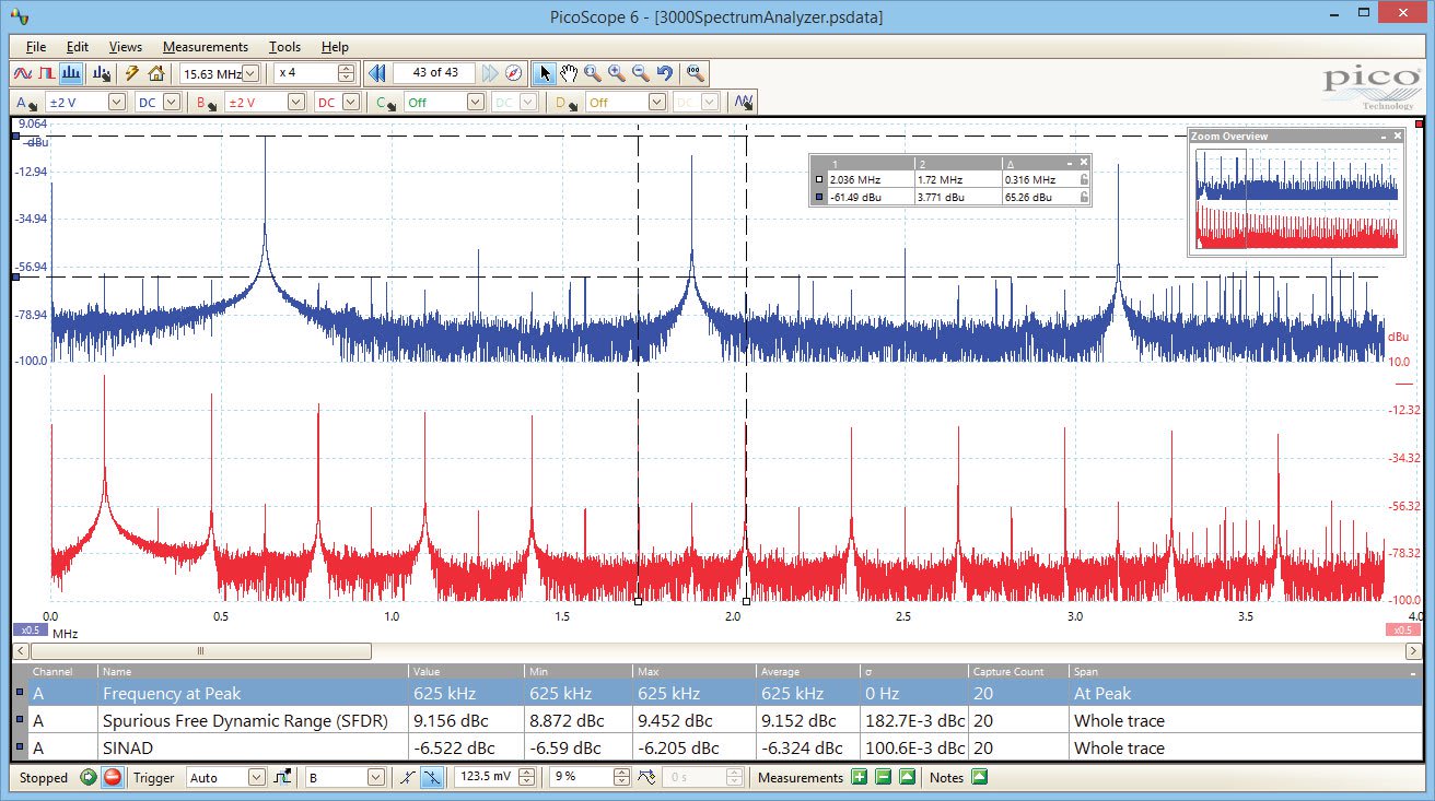
Spectrum analyzer
By simply clicking the spectrum button you can display a spectrum plot of selected channels up to the full bandwidth of the oscilloscope. A full range of settings gives you control over the number of spectrum bands, window types, and display modes (instantaneous, average, or peak hold).
You can display multiple spectrum views with different channel selections and zoom factors, and place these alongside time-domain views of the same data. A comprehensive set of automatic frequency-domain measurements can be added to the display, including THD, THD+N, SNR, SINAD and IMD. You can even use the AWG and spectrum mode together to perform swept scalar network analysis.
Most oscilloscopes are built down to a price. PicoScopes are built up to a specification.
Careful front-end design and shielding reduces noise, crosstalk, and harmonic distortion. Years of oscilloscope design experience can be seen in improved bandwidth flatness, low distortion, and excellent pulse response.
We are proud of the dynamic performance of our products, and publish their specifications in detail.
The result is simple: when you probe a circuit, you can trust in the waveform you see on the screen.
High-speed data acquisition and digitizer
The supplied drivers and software development kit (SDK) allows you to write your own software or interface to popular third-party software packages such as National Instruments’ LabVIEW and MathWorks’ MATLAB.
The driver supports data streaming, a mode which captures gap-free continuous data over USB direct to the PC at rates of up to 125 MS/s (subject to PC specifications). The capture size is limited only by available PC storage.
Beta drivers are also available for use with Raspberry Pi, BeagleBone Black, and similar ARM-powered platforms. These drivers enable you to control your PicoScope using these small, single-board Linux computers.
Benefits of USB connectivity
All PicoScope 3000D Series oscilloscopes feature a SuperSpeed USB 3.0 connection, providing high-speed data transfer whilst remaining compatible with older USB systems. A USB oscilloscope offers many benefits over a traditional benchtop device:
- Size and portability
- These compact, portable scopes are ideal for use both in the lab and in the field. Unlike traditional benchtop instruments, PicoScopes take up less space on your workbench and easily fit in to your laptop bag or tool case. PicoScope 3000D Series oscilloscopes can be powered from the USB port, removing the need to carry an external power supply.
- Flexibility
- The PicoScope software offers a breadth of advanced features via a user-friendly interface. As well as the standard Windows installation, PicoScope Beta software also works effectively on Linux and Mac operating systems, giving you the freedom to choose which platform you operate your PicoScope from.
- File sharing
- PC connectivity makes printing, copying, saving and emailing your data from the field quick and easy.
- Advanced display
- Laptop screens and desktop monitors offer higher resolution, larger size and greater flexibility for displaying your signal.
- Value
- With PicoScope you only pay for the specialized scope hardware. You don’t need to repurchase the hardware already available on your PC.
- Updates
- As the scope is connected to your computer, both the PicoScope software and the device’s firmware can be quickly updated free of charge.
- Fast transfer rates
- A USB 3.0 connection provides fast saving of waveforms when using the PicoScope software, and fast gap-free continuous streaming of up to 125 MS/s when using the SDK. The quick transfer rates ensure a fast screen update speed, even when collecting large amounts of data.
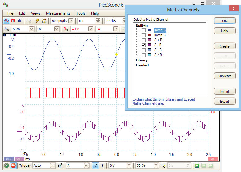
The integrated math functions of PicoScope 6 allow you to perform a variety of mathematical calculations on the input signals of your PicoScope oscilloscope. With the click of a button you can invert, add, subtract, multiply and divide channels, or create your own functions.
To add a math channel, just click a button and a wizard will guide you through the process. You can quickly select one of the built–in functions, such as inversion or addition, or open the equation editor to create complex functions involving filters (low pass, high pass, band pass and band stop filters), trigonometry, exponentials, logarithms, statistics, integrals and derivatives.
You can control the entire process using either your mouse or keyboard. With PicoScope math channels you can display up to eight real or calculated channels in each scope view. If you run out of space, just open another scope view and add more.
Custom probe settings
Custom probes allow you to correct for gain, attenuation, offsets and nonlinearities of probes, transducers, and other sensors, or convert to different measurement units such as current, power or temperature. Definitions for standard Pico-supplied probes are built in, but you can also create your own using linear scaling or even an interpolated data table, and save them for later use.
Color persistence mode
Color Persistence mode allows you to see old and new data superimposed, with new or more frequent data in a brighter color or shade. This makes it easy to see glitches and dropouts and to estimate their relative frequency. Simply click the persistence button and choose between analog intensity, digital color, and fast display modes, or create your own custom rules.
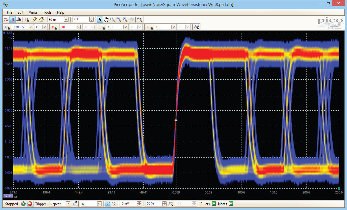
PicoScope’s new Fast Persistence mode can collect over 100 000 waveforms per second, overlaying them all with color-coding or intensity-grading to show which areas are stable and which are intermittent. Faults that previously took minutes to find now appear within seconds.
Mask limit testing
Mask limit testing allows you to compare live signals against known good signals, and is designed for production and debugging environments. Simply capture a known good signal, draw a mask around it, and then attach the system under test. PicoScope will capture any intermittent glitches and can show a failure count and other statistics in the Measurements window.
The numerical and graphical mask editors can be used separately or in combination, allowing you to enter accurate mask specifications, modify existing masks, and import and export masks as files.
Automatic measurements
PicoScope allows you to display a table of calculated measurements for troubleshooting and analysis.
Using the built-in measurement statistics you can see the average, standard deviation, maximum and minimum of each measurement as well as the live value. You can add as many measurements as you need on each view. For a full list of the measurements available in both scope and spectrum modes, see Automatic Measurements in the Specifications table.
PicoScope 3000 Series Application examples
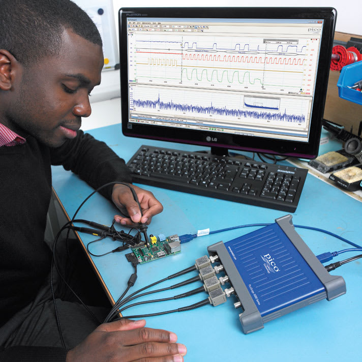
Testing on the move
The PicoScope 3000 Series oscilloscopes slip easily into a laptop bag, so you don’t need to carry bulky benchtop instruments to perform on-site troubleshooting. Being powered via a USB connection, your PicoScope can simply be plugged into your laptop and used for measuring wherever you are. The PC connection also makes saving and sharing your data quick and easy: in a matter of seconds you can save your scope traces to review later, or attach the complete data file to an email for analysis by other engineers away from the test site. As PicoScope 6 is free to download by anyone, colleagues can use the full capabilities of the software, such as serial decoding and spectrum analysis, without needing an oscilloscope themselves.
Embedded debugging
You can test and debug a complete signal-processing chain using a PicoScope 3406D MSO.
Use the built-in arbitrary waveform generator (AWG) to inject single-shot or continuous analog signals. The response of your system can then be observed in both the analog domain, using the four 200 MHz input channels, and in the digital domain with 16 digital inputs at up to 100 MHz. Follow the analog signal through the system while simultaneously using the built-in serial decoding function to view the output of an I2C or SPI ADC.
If your system drives a DAC in response to the analog input changing, you can decode the I2C or SPI communication to that as well as its analog output. This can all be performed simultaneously using the 16 digital and 4 analog channels.
Using the deep 512 MS buffer memory, you can capture the complete response of your system without sacrificing the sampling rate, and zoom in on the captured data to find glitches and other points of interest.
Oscilloscopes/Mixed Signal Oscilloscopes (MSO) Template | |
|---|---|
| Channels | 2 |
| Bandwidth | 200 MHz |
| Sampling Rate | 1 GS/S |
| Rise Time | 1.75 ns |
| # Logic Channels | 16 EA |
| Bits | 8 |
Product General Attributes | |
| Warranty | 5 YEARS |
| Safety Approval | CE, RoHS |
| Interfaces I/O | Analog Input , USB |
| Product Weight | 1.2 LBS |
| Product Height | 1.6 IN |
| Product Length | 7.5 IN |
| Product Width | 6.7 IN |
| Shipping Weight | 4 LBS |
| HTS/Schedule B Number | 90302000 |
| Calibration Included | Factory Calibration |
| Country of Origin | United Kingdom |
| Shipping Height | 3.95 IN |
| Shipping Length | 11.95 IN |
| Shipping Width | 7.25 IN |
You must be logged in to post a review.
Manuals/Guides
| Weight | 1.2 lbs |
|---|---|
| Dimensions | 7.5 × 6.7 × 1.6 in |
Related products

Sale
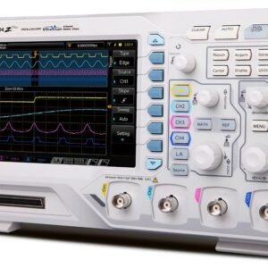
Rigol DHO814 – Digital Oscilloscope (4 Channels / 100MHz)
Original price was: $603.90.$513.31Current price is: $513.31. Add to cartSale

Rigol DHO802 – Digital Oscilloscope (2 Channels / 70MHz)
Original price was: $361.90.$307.61Current price is: $307.61. Add to cartSale

Tektronix TBS1102C – Digital Storage Oscilloscope (100 MHz, 1 GS/s)
Original price was: $1,408.00.$1,337.60Current price is: $1,337.60. Add to cart Pico 3206D MSO PicoScope 200 M...
 $2,150.50
Our team of knowledgeable professionals is here to help you make informed decisions. Whether you need product recommendations, technical support, or guidance on your purchase, we're just a click away.
Contact Us Now:
📧 sales@nestesinstruments.com
📞 +1 (833) 763-7837
Let us assist you in finding the perfect solution!
Contact Us Now:
📧 sales@nestesinstruments.com
📞 +1 (833) 763-7837
Let us assist you in finding the perfect solution!
Reviews
There are no reviews yet.