No products in the cart.


Description
Pico 5242D MSO – 60 MHz 2-Channel Mixed-Signal Oscilloscope
- Deep capture memory – 128 million samples
- 2 channels
- Mixed-signal models add 16 digital channels
- Serial decoding – analyze 18 protocols
- USB 3.0 connection for continuous high-speed data streaming
- Small, light and portable
Today’s electronic designs employ a wide range of signal types: analog, digital, serial (both high- and low-speed), parallel, audio, video, power distribution, and so on. All need to be debugged, measured, and validated to ensure that the device under test is functioning correctly and within specification.
To handle this variety of signal types, PicoScope 5000D Series FlexRes oscilloscopes provide 8 to 16 bits of vertical resolution, with up to 200 MHz bandwidth and 1 GS/s sampling speed. You select the most appropriate hardware resolution for the requirements of each measurement.
PicoScopes include advanced features such as mask limit testing, serial decoding, advanced triggering, automatic measurements, math channels (including the ability to plot frequency and duty cycle against time), XY mode and segmented memory. The PicoScope 5000D Series also benefits from Pico’s award-winning DeepMeasure feature and FlexRes flexible resolution.
Supported by the free and regularly updated PicoScope 6 software, these devices offer an ideal, cost-effective package for many applications, including design, research, test, education, service and repair.
What is FlexRes?
Pico FlexRes flexible resolution oscilloscopes allow you to reconfigure the scope hardware to increase either the sampling rate or the resolution.
This means you can reconfigure the hardware to be either a fast (1 GS/s) 8-bit oscilloscope for looking at digital signals or a high-resolution 16-bit oscilloscope for audio work and other analog applications. Whether you’re capturing and decoding fast digital signals or looking for distortion in sensitive analog signals, FlexRes oscilloscopes are the answer.

Advanced display
PicoScope 6 software dedicates the majority of the display area to the waveform, ensuring that the maximum amount of data is visible at all times. The size of the display is only limited by the size of your computer’s monitor, so even with a laptop, the viewing area is much bigger, with much higher resolution, than that of a benchtop scope. With such a large display area available, you can create a customizable split-screen display and view multiple channels or different views of the same signal at the same time – the software can even show multiple oscilloscope and spectrum analyzer views at once.
Each view has separate zoom, pan and filter settings for ultimate flexibility. You can control the PicoScope 6 software using a mouse, touchscreen or customizable keyboard shortcuts.

Low-level signals
With its 16-bit resolution, the PicoScope 5000D Series can magnify low-level signals at high zoom factors. This allows you to view and measure features such as noise and ripple superimposed on larger DC or low-frequency voltages. Additionally, you can use the Lowpass Filtering controls on each channel independently, to hide noise and reveal the underlying signal.

High bandwidth, high sampling rate
Many USB-powered oscilloscopes have real-time sampling rates of only 100 or 200 MS/s, but the PicoScope 5000D Series offers up to 1 GS/s, and a maximum bandwidth of 200 MHz. Equivalent time sampling (ETS) mode can be used to further boost the effective sampling rate to 10 GS/s for a more detailed view of repetitive signals.
Deep capture memory
PicoScope 5000D Series oscilloscopes have waveform capture memories ranging from 128 megasamples to 512 megasamples – many times larger than competing scopes. Deep memory enables the capture of long-duration waveforms at maximum sampling speed. In fact, the PicoScope 5000D Series can capture waveforms over 500 ms long with 1 ns resolution. In contrast, the same 500 ms waveform captured by an oscilloscope with a 10 megasample memory would have just 50 ns resolution.
Deep memory can be useful in other ways too: PicoScope 6 lets you divide the capture memory into a number of segments, up to a maximum of 10 000. You can set up a trigger condition to store a separate capture in each segment, with as little as 1 µs dead time between captures. Once you have acquired the data, you can step through the memory one segment at a time until you find the event you are looking for.
Powerful tools are included to allow you to manage and examine all of this data. As well as functions such as mask limit testing and color persistence mode, the PicoScope 6 software enables you to zoom into your waveform by a factor of several million. The Zoom Overview window allows you to easily control the size and location of the zoom area. Other tools, such as the waveform buffer, serial decoding and hardware acceleration work with the deep memory, making the PicoScope 5000D some of the most powerful oscilloscopes on the market.

DeepMeasure
The PicoScope 6 DeepMeasure tool uses deep memory to analyze every cycle contained in each triggered waveform acquisition. It displays the results in a table, with the parameter fields shown in columns and waveform cycles shown in rows: you can easily sort the results by any parameter and correlate them with the waveform display.
The current version of the tool includes sixteen parameters per cycle, and can display up to a million cycles. Parameters include cycle time, frequency, pulse width, duty cycle, rise and fall time, overshoot, undershoot, max voltage and min voltage. Start and end times relative to the trigger are given for each cycle.

Waveform buffer and navigator
Ever spotted a glitch on a waveform, but by the time you’ve stopped the scope it’s gone? With PicoScope you no longer need to worry about missing glitches or other transient events, as it can store the last 10 000 waveforms in its circular waveform buffer.
The buffer navigator provides an efficient way of navigating and searching through waveforms, effectively letting you turn back time. When carrying out a mask limit test, you can also set the navigator to show only mask fails, enabling you to find any glitches quickly.
Mixed-signal models
The PicoScope 5000D MSO models add 16 digital channels to the 2 or 4 analog channels, enabling you to accurately time-correlate analog and digital channels. Digital channels may be grouped and displayed as a bus, with each bus value displayed in hex, binary or decimal or as a level (for DAC testing). You can set advanced triggers across both the analog and digital channels.
The digital inputs also bring extra power to the serial decoding options. You can decode serial data on all analog and digital channels simultaneously, giving you up to 20 channels of data – for example decoding multiple SPI, I2C, CAN bus, LIN bus and FlexRay signals all at the same time.

Persistence mode
PicoScope 6 persistence mode options allow you to see old and new data superimposed, with newer waveforms drawn in a brighter color or deeper shade. This makes it easy to spot glitches and dropouts and estimate their relative frequency – useful for displaying and interpreting complex analog signals such as video waveforms and analog modulation signals.
The PicoScope 5000D Series’ HAL3 hardware acceleration means that, in Fast Persistence mode, waveform update rates of up to 130 000 waveforms per second are achievable.

Arbitrary waveform and function generator
All PicoScope 5000D units have a built-in 14-bit 200 MS/s arbitrary waveform generator (AWG). You can create and adapt arbitrary waveforms using the built-in editor, import them from existing oscilloscope traces, or load a waveform from a spreadsheet.
The AWG can also act as a function generator with a range of standard output signals, including sine, square, triangle, DC level, white noise and PRBS. As well as the basic controls to set level, offset and frequency, more advanced controls allow you to sweep over a range of frequencies. Combined with the spectrum peak hold option, this makes a powerful tool for testing amplifier and filter responses.
Trigger tools allow you to output one or more cycles of a waveform when various conditions are met, such as the scope triggering or a mask limit test failing.

Serial decoding and analysis
With its deep memory, the PicoScope 5000D Series is ideally suited to serial decoding and analysis, which are included as standard. The PicoScope 6 software has support for 18 protocols including I2C, SPI, CAN, RS-232 and Ethernet. Decoding helps you see what is happening in your design to identify programming and timing errors and check for other signal integrity issues. Timing analysis tools help to show the performance of each design element, identifying parts of the design that need to be improved to optimize overall system performance.

Spectrum analyzer
The spectrum view plots amplitude against frequency and is ideal for finding noise, crosstalk or distortion in signals. PicoScope 6 uses a fast Fourier transform (FFT) spectrum analyzer, which (unlike a traditional swept spectrum analyzer) can display the spectrum of a single, non- repeating waveform.
With a click of a button, you can display a spectrum plot of the active channels, with a maximum frequency of up to 200 MHz. A comprehensive range of settings gives you control over the number of spectrum bins, window functions, scaling (including log/log) and display mode (instantaneous, average or peak-hold).
Display multiple spectrum views with different channel selections and zoom factors, and place these alongside time- domain views of the same data. Choose from a number of automatic frequency- domain measurements to add to the display, including THD, THD+N, SNR, SINAD and IMD. You can apply mask limit testing to a spectrum and can even use the AWG and spectrum mode together to perform swept scalar network analysis.

Advanced triggers
The PicoScope 5000D Series offers an industry-leading set of advanced triggers including pulse width, runt pulse, windowed and dropout.
The digital trigger available on MSO models allows you to trigger the scope when any or all of the 16 digital inputs match a user-defined pattern. You can specify a condition for each channel individually, or set up a pattern for all channels at once using a hexadecimal or binary value.
You can also use the logic trigger to combine the digital trigger with an edge or window trigger on any of the analog inputs, for example to trigger on data values in a clocked parallel bus.

Digital triggering architecture
In 1991, Pico Technology pioneered the use of digital triggering and precision hysteresis using the actual digitized data. Traditionally, digital oscilloscopes have used an analog trigger architecture based on comparators, which can cause time and amplitude errors that cannot always be calibrated out. Additionally, the use of comparators can often limit the trigger sensitivity at high bandwidths and can create a long trigger rearm delay.
Pico’s technique of fully digital triggering reduces trigger errors and allows our oscilloscopes to trigger on the smallest signals, even at the full bandwidth, so you can set trigger levels and hysteresis with high precision and resolution.
The digital trigger architecture also reduces the rearm delay. Combined with the segmented memory, this enables you to use rapid triggering to capture 10 000 waveforms in 10 ms in 8-bit mode.

SuperSpeed USB 3.0 connection
PicoScope 5000D Series oscilloscopes feature a USB 3.0 connection, providing lightning- fast saving of waveforms while retaining compatibility with older USB standards. The PicoSDK software development kit supports continuous streaming to the host computer at rates up to 125 MS/s.
Connections:
The front panel of the 2-channel PicoScope 5000D Series oscilloscopes has:
- 2 x BNC analog input channels
- 1 x probe compensation pin
- 1 x BNC external trigger input
- 1 x BNC AWG/function generator output
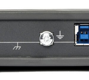
The rear panel has:
- 1 x ground terminal
- 1 x USB 3.0 port


The front panel of the 4-channel PicoScope 5000D Series oscilloscopes has:
- 4 x BNC analog input channels
- 1 x probe compensation pin
- 1 x BNC external trigger input
- 1 x BNC AWG/function generator output
The rear panel has:
- 1 x ground terminal
- 1 x USB 3.0 port
- 1 x DC power input

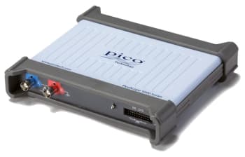
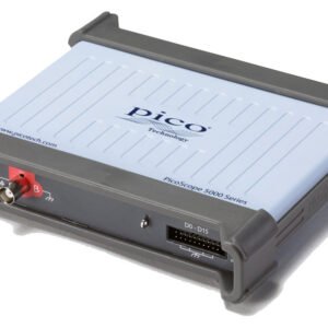
The front panel of the 2-channel PicoScope 5000D MSO Series oscilloscopes has:
- 2 x BNC analog input channels
- 1 x probe compensation pin
- 16 digital inputs
The rear panel has:
- 1 x BNC AWG/function generator output
- 1 x ground terminal
- 1 x USB 3.0 port

The front panel of the 4-channel PicoScope 5000D MSO Series oscilloscopes has:
- 4 x BNC analog input channels
- 1 x probe compensation pin
- 16 digital inputs
The rear panel has:
- 1 x BNC AWG/function generator output
- 1 x ground terminal
- 1 x USB 3.0 port
- 1 x DC power input
Oscilloscopes/Mixed Signal Oscilloscopes (MSO) Template | |
|---|---|
| Channels | 2 |
| Bandwidth | 60 MHz |
| Sampling Rate | 1 GS/S |
| Rise Time | 5.8 ns |
| # Logic Channels | 16 EA |
| Bits | 16 |
Product General Attributes | |
| HTS/Schedule B Number | 90302000 |
| ECCN Number | 3A992 |
| Country of Origin | United Kingdom |
You must be logged in to post a review.
Manuals/Guides
ManualsSpec Sheets
Related products

Sale
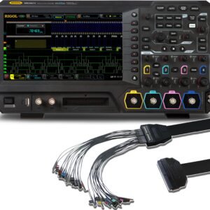
Rigol MSO5074 LA KIT – Four Channel, 70 MHz Mixed Signal Oscilloscope with PLA2216 Logic Probe
Original price was: $1,537.80.$1,427.80Current price is: $1,427.80. Add to cartSale

Rigol DHO802 – Digital Oscilloscope (2 Channels / 70MHz)
Original price was: $361.90.$307.61Current price is: $307.61. Add to cartSale

Tektronix TBS1102C – Digital Storage Oscilloscope (100 MHz, 1 GS/s)
Original price was: $1,408.00.$1,337.60Current price is: $1,337.60. Add to cart
 Pico 5242D MSO – 60 MHz ...
 $1,864.50
Our team of knowledgeable professionals is here to help you make informed decisions. Whether you need product recommendations, technical support, or guidance on your purchase, we're just a click away.
Contact Us Now:
📧 sales@nestesinstruments.com
📞 +1 (833) 763-7837
Let us assist you in finding the perfect solution!
Contact Us Now:
📧 sales@nestesinstruments.com
📞 +1 (833) 763-7837
Let us assist you in finding the perfect solution!
Reviews
There are no reviews yet.