No products in the cart.


Description

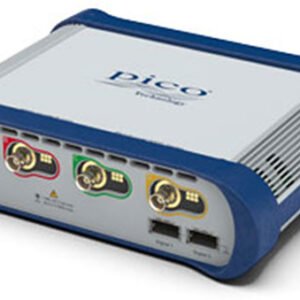
Pico Technology 6424E-D4
- 500 MHz PC USB oscilloscope with 4 analog channels, 8-12-bit resolution (FlexRes), and 4 GS capture memory
- Up to 16 digital channels with TA369 pods (sold separately)
- Function generator (Up to 50 MHz for sine/square waves; 10 MHz for other waves)
- Arbitrary waveform generator (50 MHz, 200 MS/s, 14-bit)
- Spectrum analyzer (DC to 500 MHz)
PC USB Oscilloscope, 500 MHz, 4CH, 8-12Bits, 4GS, without probes
Ultra-Deep-Memory, High-Performance Oscilloscopes and MSOs
The PicoScope 6000E Series fixed-resolution and FlexRes oscilloscopes provide up to 12 bits (select models) of vertical resolution, 1 GHz bandwidth, and 5 GS/s sampling rate. See individual models for specifications.
Models with four or eight analog channels have the timing and amplitude resolution you need to reveal critical signal integrity issues such as timing errors, glitches, dropouts, crosstalk, and metastability issues.
These instruments, with PicoScope software, are ideal for design engineers working with high-performance embedded systems, signal processing, power electronics, mechatronics and automotive designs, and for researchers and scientists working on multichannel high-performance experiments in physics labs, particle accelerators, and similar facilities.
Several Versions Available
The PicoScope 6000E series consists of several models differing in number of channels, sample size, frequency, and memory. Please see the table below for a comparison of the models and some of their key differences.
| Model | Order Code | Channels | Frequency | Sample Size | Memory |
| 6403E-D4 | PQ243 | 4 | 300 MHz | 8 bit | 1 GS |
| 6404E-D4 | PQ244 | 4 | 500 MHz | 8 bit | 2 GS |
| 6424E-D4 | PQ245 | 4 | 500 MHz | 8/10/12 bit | 4 GS |
| 6804E-D4 | PQ241 | 8 | 500 MHz | 8 bit | 2 GS |
| 6824E-D4 | PQ242 | 8 | 500 MHz | 8/10/12 bit | 4 GS |
| 6405E-D4 | PQ304 | 4 | 750 MHz | 8 bit | 2 GS |
| 6425E-D4 | PQ306 | 4 | 750 MHz | 8/10/12 bit | 4 GS |
| 6406E-D4 | PQ305 | 4 | 1 GHz | 8 bit | 2 GS |
| 6426E-D4 | PQ307 | 4 | 1 GHz | 8/10/12 bit | 4 GS |
| 6428E-D | PQ344 | 4 | 3 GHz | 8/10/12 bit | 4 GS |

Inputs, Outputs, and Indicators
Front Panel (8-channel oscilloscope shown, your model may differ)
1. Input channels A to H
2. Probe compensation output
3. Probe compensation ground
4. Power LED
5. Status/trigger LED
6. Intelligent probe interfaces
7. Digital 1 & 2 MSO pod interfaces – accept TA369 MSO pods
Rear Panel
1. Aux Trig – trigger from an external logic-level source and integrate the scope into a larger system
2. USB 3.0 port
3. 12 V DC input – use only the mains power adaptor supplied with the oscilloscope
4. AWG output 50 MHz 14 bits 200 MS/s
5. 10 MHz clock reference input. The scope will automatically switch to the external reference when a clock signal is detected
6. Ground – accepts bare wire or 4 mm (banana) plug


Mixed-Signal Operation (With Optional MSO Pods – Sold Separately)
When fitted with optional 8-channel TA369 MSO pods, the PicoScope 6000E Series adds up to 16 high-performance digital channels to up to eight analog channels, enabling you to accurately time-correlate analog and digital channels. Digital channel bandwidth is 500 MHz, equivalent to 1 Gb/s, and the input capacitance of only 3.5 pF minimizes loading on the device under test.
Digital channels, captured from either parallel or multiple serial buses, may be grouped and displayed as a bus, with each bus value displayed in hex, binary or decimal, or as a level (for DAC testing). You can set advanced triggers across the analog and digital channels.
The digital inputs also bring extra power to the serial decoding feature. You can decode serial data on all analog and digital channels simultaneously, giving you up to 24 channels of data – for example, decoding multiple SPI, I²C, CAN bus, LIN bus, and FlexRay signals all at the same time.
PicoScope/PicoLog/PicoSDK Software
PicoScope PC-based instruments use the host computer’s display, which is typically larger and of higher resolution than the dedicated displays installed in traditional benchtop oscilloscopes. This allows room for simultaneous display of time- and frequency-domain waveforms, decoded serial bus tables, measurement results with statistics and more. Large, high-resolution displays really come into their own when viewing high-resolution signals with the PicoScope 6000E 12-bit FlexRes models. With a 4K monitor, PicoScope can display more than ten times the information of some of our competitors’ scopes, solving the problem of how to match a big display and features with a small-footprint portable oscilloscope.
PicoLog allows sample rates of up to 1 kS/s per channel, and is ideal for long-term observation of general parameters, such as voltage or current levels, on several channels at the same time, whereas the PicoScope software is more suitable for waveshape or harmonic analysis. You can also use PicoLog to view data from your oscilloscope alongside a data logger or other device. For example, you could measure voltage and current with your PicoScope and plot both against temperature using a TC-08 thermocouple data logger, or humidity with a DrDAQ multipurpose data logger and suitable sensor.
The free PicoSDK software development kit allows you to write your own software and includes drivers for Windows, macOS and Linux. Example code supplied on our GitHub organization page shows how to interface to third-party software packages such as National Instruments LabVIEW and MathWorks MATLAB. Among other features, the drivers support data streaming, a mode that captures continuous gap-free data directly to your PC or host computer at rates of over 300 MS/s, so you are not limited by the size of your scope’s capture memory. Sampling rates in streaming mode are subject to PC specifications and application loading.


Flexible Resolution (FlexRes – Available on Select Products)
Pico FlexRes flexible-resolution oscilloscopes allow you to reconfigure the scope hardware to optimize either the sampling rate or the resolution. This means you can reconfigure the hardware to be either a fast (5 GS/s) 8-bit oscilloscope for looking at digital signals, a 10-bit oscilloscope for general-purpose use or a high-resolution 12-bit oscilloscope for audio work and other analog applications.
Whether you’re capturing and decoding fast digital signals or looking for distortion in sensitive analog signals, FlexRes oscilloscopes are the answer. FlexRes is included on the 8-channel PicoScope 6824E and the 4-channel PicoScope 6424E, 6425E, and 6426E oscilloscopes.
Resolution enhancement—a digital signal processing technique built into PicoScope — can further increase the effective vertical resolution of the scope to 16 bits.
Most digital oscilloscopes gain their high sampling rates by interleaving multiple 8-bit ADCs. This interleaving process introduces errors that always make the dynamic performance worse than that of the individual ADC cores.
The FlexRes architecture employs multiple high‑resolution ADCs at the input channels in different time-interleaved and parallel combinations to optimize, for example, the sampling rate to 10 GS/s at 8 bits or the resolution to 12 bits at 1.25 GS/s.
Serial Bus Decoding and Protocol Analysis
PicoScope can decode 1-Wire, ARINC 429, BroadRReach, CAN, CAN FD, CAN J1939, CAN XL, DALI, DCC, DMX512, Ethernet 10BASE-T, Extended UART, Fast Ethernet 100BASE-TX, FlexRay, I2C, I2S, I3C BASIC v1.0, LIN, Manchester, MIL-STD-1553, MODBUS ASCII, MODBUS RTU, NMEA-0183, Parallel Bus, PMBus, PS/2, PSI5 (Sensor), Quadrature, RS232/UART, SBS Data, SENT Fast, SENT Slow, SENT SPC, SMBus, SPI-MISO/MOSI, SPI-SDIO, USB (1.0/1.1) and Wind Sensor protocol data as standard, with more protocols in development and available in the future, with free-of-charge software upgrades.
Graph format shows the decoded data (in hex, binary, decimal or ASCII) in a data-bus timing format beneath the waveform on a common time axis, with error frames marked in red. These frames can be zoomed to investigate noise or signal integrity issues.
Table format shows a list of the decoded frames, including the data and all flags and identifiers. You can set up filtering conditions to display only the frames you are interested in or search for frames with specified properties. The statistics option reveals more detail about the physical layer such as frame times and voltage levels. PicoScope can also import a spreadsheet to decode the data into user-defined text strings.


Spectrum Analyzer
The spectrum view plots amplitude against frequency and is ideal for finding noise, crosstalk, or distortion in signals. The spectrum analyzer in PicoScope is of the Fast Fourier Transform (FFT) type which, unlike a traditional swept spectrum analyzer, can display the spectrum of a single, non-repeating waveform. With up to a million points, PicoScope’s FFT has excellent frequency resolution and a low noise floor.
With a click of a button, you can display a spectrum plot of the active channels, with a maximum frequency up to the bandwidth of your scope. A full range of settings gives you control over the number of spectrum bands (FFT bins), scaling (including log/log), and display modes (instantaneous, average, or peak-hold). A selection of window functions allow you to optimize for selectivity, accuracy or dynamic range.
You can display multiple spectrum views alongside oscilloscope views of the same data. A comprehensive set of automatic frequency-domain measurements can be added to the display, including THD, THD+N, SNR, SINAD, and IMD. A mask limit test can be applied to a spectrum and you can even use the AWG and spectrum mode together to perform swept scalar network analysis.
Arbitrary Waveform and Function Generator
All PicoScope 6000E models have a built-in 50 MHz function (sine and square wave) generator, with triangle, DC level, white noise, PRBS and other waveforms possible at lower frequencies. As well as basic controls to set level, offset and frequency, more advanced controls allow you to sweep over a range of frequencies. Combined with the spectrum peakhold option, this makes a powerful tool for testing amplifier and filter responses.
Trigger tools allow one or more cycles of a waveform to be output when various conditions are met, such as the scope triggering, a trigger event on the aux input, or a mask limit test failing.
All models also include a 14-bit 200 MS/s arbitrary waveform generator (AWG). This has a variable sample clock, which avoids the jitter on waveform edges seen with fixed-clock generators and allows generation of accurate frequencies down to 100 μHz. AWG waveforms can be created or edited using the built-in editor, imported from oscilloscope traces, loaded from a spreadsheet or exported to a CSV file.

Oscilloscopes/Digital Oscilloscopes Template | |
|---|---|
| Bandwidth | 500 MHz |
| Channels | 4 |
| Sampling Rate | 5 GS/S |
| Memory | 4000 MP [megapoints] (4096000 kB) |
| Rise Time | 850 ns |
| # Logic Channels | 16 EA # Logic Channels With optional pods |
| Waveforms per second | 300,000 |
Oscilloscopes/PC Based Oscilloscopes Template | |
| Bits | 12 |
Product General Attributes | |
| Warranty | 5 YEARS |
| Interfaces I/O | USB |
| Data Logging | Yes |
| Power Supply Voltage | 120V 50/60 Hz |
You must be logged in to post a review.
Manuals/Guides
Related products


 Pico Technology 6424E-D4 ̵...
 $9,564.50
Our team of knowledgeable professionals is here to help you make informed decisions. Whether you need product recommendations, technical support, or guidance on your purchase, we're just a click away.
Contact Us Now:
📧 sales@nestesinstruments.com
📞 +1 (833) 763-7837
Let us assist you in finding the perfect solution!
Contact Us Now:
📧 sales@nestesinstruments.com
📞 +1 (833) 763-7837
Let us assist you in finding the perfect solution!
Reviews
There are no reviews yet.