No products in the cart.


Description
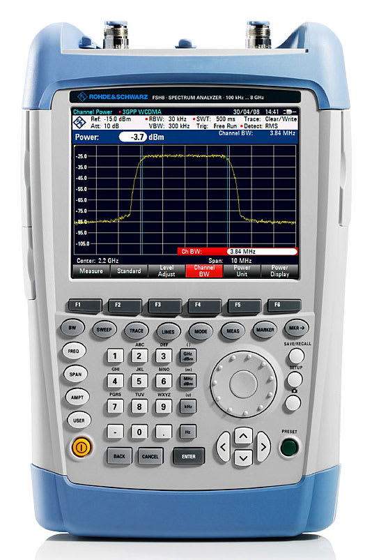
Rohde and Schwarz FSH13.23 – Handheld Spectrum Analyzer (9 kHz-13.6 GHz) with Tracking Generator, VSWR Bridge
- Handheld spectrum analyzer
- Catalog number 1314.2000.23
- Frequency range: 9 kHz-13.6 GHz
- Includes pre-amplifier, tracking generator and built-in VSWR bridge
- Please click here for a list of models, options and option/model compatibility
The R&S FSH is a handheld spectrum analyzer and – depending on the model and the options installed – a power meter, a cable and antenna tester and a two-port vector network analyzer. It provides the most important RF analysis functions that an RF service technician or an installation and maintenance team needs to solve daily routine measurement tasks. For example, it can be used for maintaining or installing transmitter systems, checking cables and antennas, assessing signal quality in broadcasting, radio communications and service, measuring electric field strength or in simple lab applications. The R&S FSH can perform any of these tasks quickly, reliably and with high measurement accuracy.
Weighing only 3 kg, the R&S FSH is a handy instrument. All frequently used functions have their own function keys and are within fingertip reach. The brilliant color display is easy to read even under poor lighting conditions, and it has a monochrome mode for extreme conditions.
The capacity of the R&S FSH battery enables uninterrupted operation for up to 4.5 hours. The battery is changed within seconds and all connectors are splash-proof.
Several models available
The Rohde and Schwarz FSH is available in a variety of formats, covering several frequency ranges and with multiple configurations of each. The chart below provides a brief overview of several main configuration options. Please see the attached brochure and specification sheet for more detailed information.
Altogether ten R&S FSH models for different applications and frequency ranges are available. The R&S FSH can perform measurements up to an upper frequency limit of 3.6 GHz, 8 GHz, 13.6 GHz or 20 GHz.
Models featuring a built-in tracking generator can also be used to determine the transmission characteristics of cables, filters, amplifiers, etc. Additional models with built-in tracking generator and internal VSWR bridge are available for distance-to-fault (DTF) measurements, matching measurements and vector network analysis.
| Model | Catalog | Frequency | Pre-amplifier | Tracking Generator | Built in VSWR bridge | DC voltage supply (bias) for port 1/2 |
| FSH4.04 | 1309.6000.04 | 9kHz – 3.6GHz | ✔ | |||
| FSH4.14 | 1309.6000.14 | 9kHz – 3.6GHz | ✔ | ✔ | ||
| FSH4.24 | 1309.6000.24 | 100kHz – 3.6GHz | ✔ | ✔ | ✔ | ✔ |
| FSH8.08 | 1309.6000.08 | 9kHz – 8GHz | ✔ | |||
| FSH8.18 | 1309.6000.18 | 9kHz – 8GHz | ✔ | ✔ | ||
| FSH8.28 | 1309.6000.28 | 100kHz – 8GHz | ✔ | ✔ | ✔ | ✔ |
| FSH13.13 | 1314.2000.13 | 9kHz – 13.6GHz | ✔ | |||
| FSH13.23 | 1314.2000.23 | 9kHz – 13.6GHz | ✔ | ✔ | ✔ | |
| FSH20.20 | 1314.2000.20 | 9kHz – 20GHz | ✔ | |||
| FSH20.30 | 1314.2000.30 | 9kHz – 20GHz | ✔ | ✔ | ✔ |
Standard functions
This chart provides an overview of standard functions for the different FSH models.
| Models | .04/.08/.13/.20 | .14/.18 | .24/.28 | .23/.30 |
| TDMA power measurements | • | • | • | • |
| Channel power measurements | • | • | • | • |
| Field strength measurements/measurements with isotropic antennas | • | • | • | • |
| Occupied bandwidth measurements | • | • | • | • |
| Frequency settings via channel tables | • | • | • | • |
| Scalar transmission measurements | – | • | • | – |
| Scalar reflection measurements | – | – | • | – |
| Vector transmission (S12) and reflection (S22) measurements | – | – | – | • |
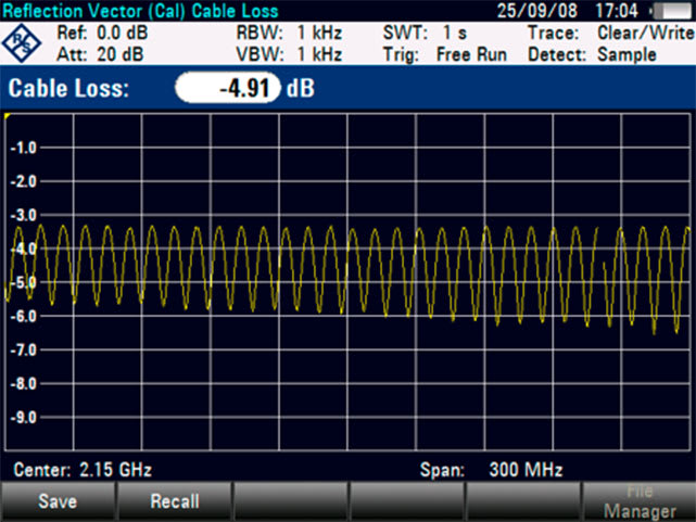
| One-port cable loss measurements | – | – | – | • |
| Channel power meter | • | • | • | • |
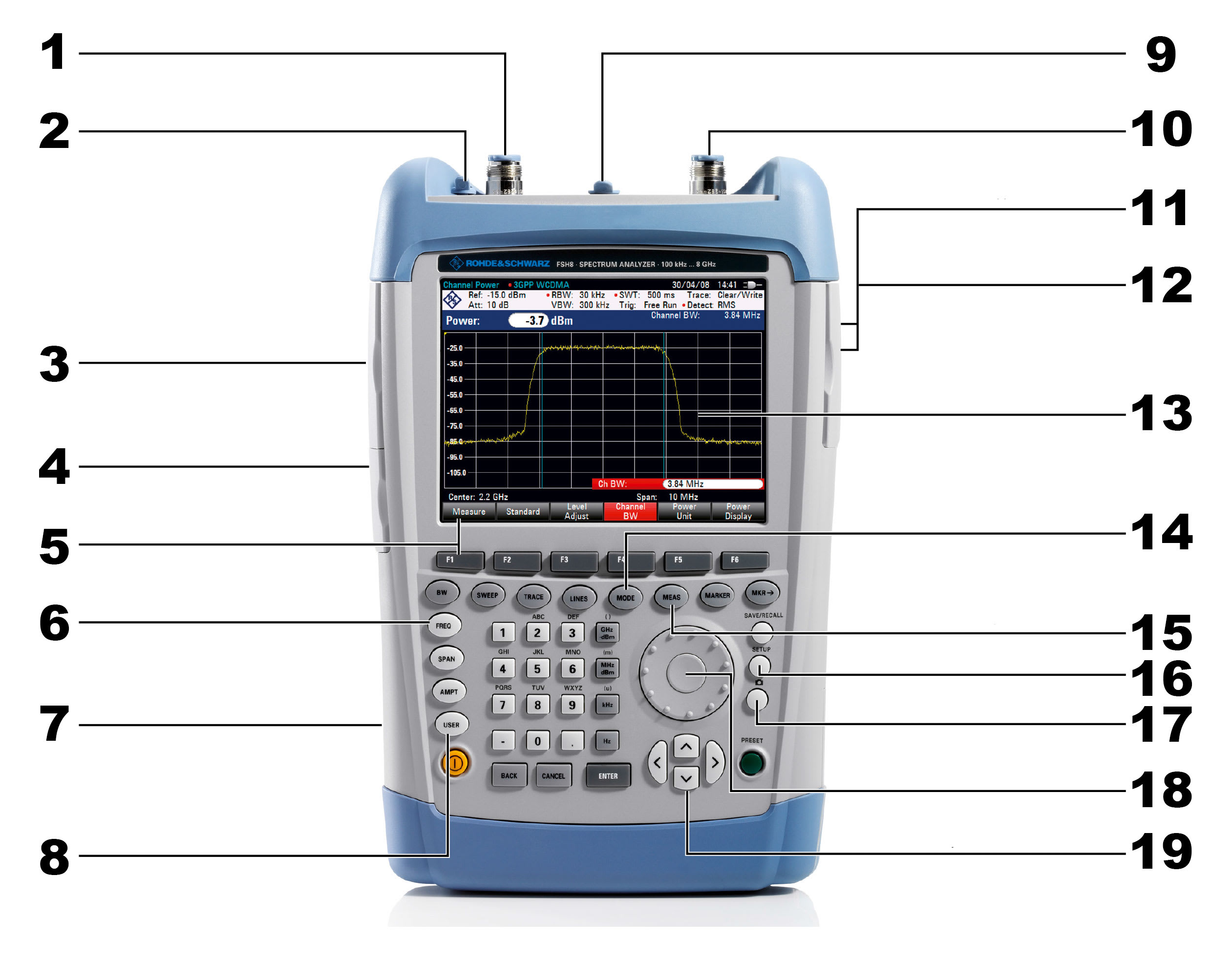
- RF input
- Connector for headphones
- Inputs
- Ext. trigger input
- Ext. reference input
- IF output
- Bias input
- Connector for accessories
- LAN/USB interface
- Simple menu based operation via softkeys
- Function keys
- Kensington lock
- Call-up of user-defined settings
- Connector for power sensor
- Tracking generator output
- USB interface, type A
- SD memory card
- Color LCD (640 × 480 pixel), can be switched to high-contrast monochrome display in extreme sunlight
- Selection between different operating modes (spectrum analyzer, vector network analyzer, power meter, etc.)
- Selection of the measurement function (channel power, occupied bandwidth, etc.)
- General instrument setup
- Screenshot
- Rotary knob with Enter button
- Cursor keys
Please note, the sections below show only a portion of the FSH’s capabilities. ***Some of the testing methods shown below require additional software and are only possible with certain FSH models. Please click here for a breakdown of models, software options and compatibility. For more detailed information, please see the brochure in the documents section of this page.***
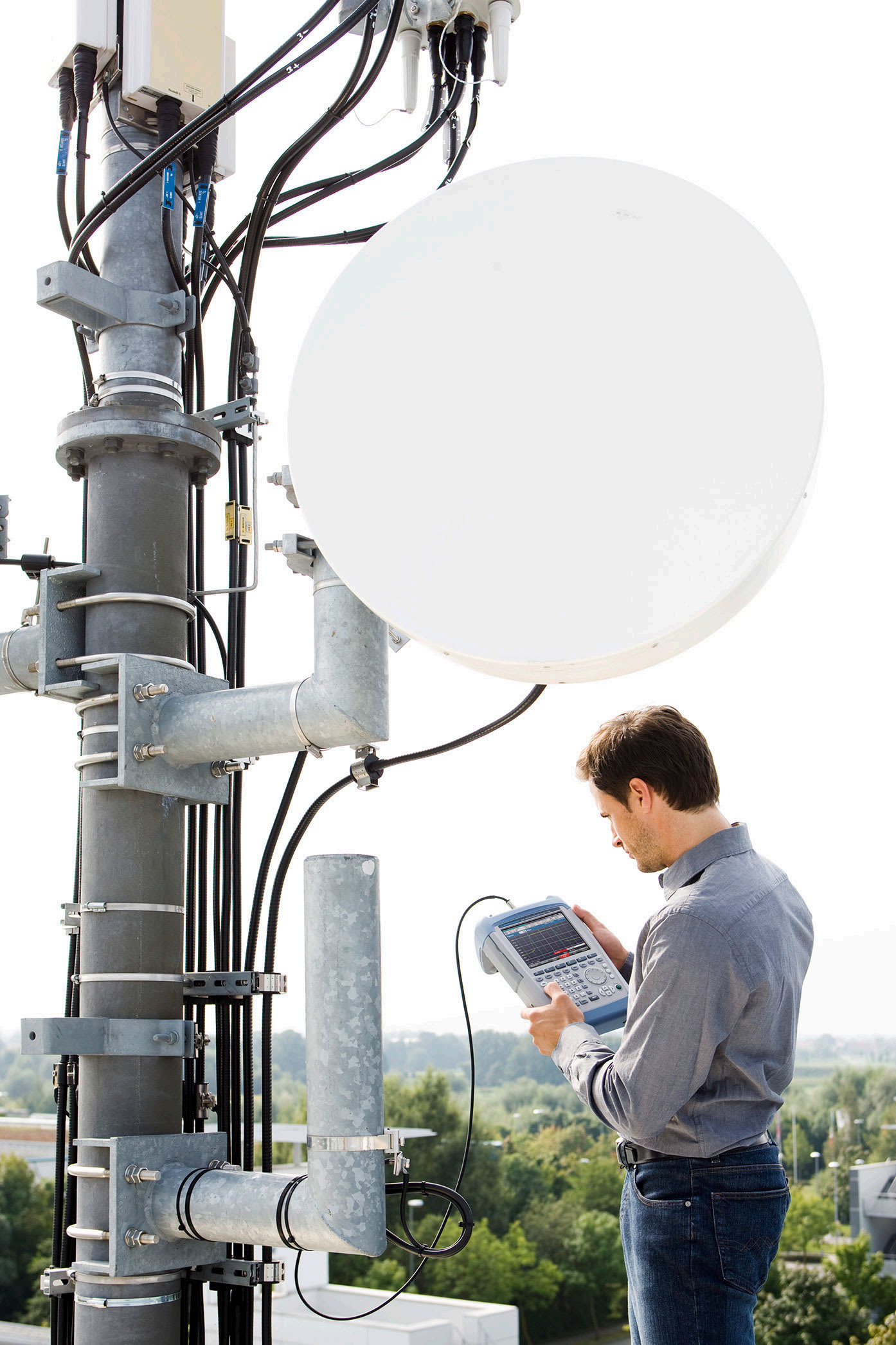
Installation and maintenance of transmitter stations
The R&S FSH is designed for the installation and maintenance of transmitter systems. It provides the following measurement functions:
- Checking of signal quality in the spectral and time domain using channel power measurements and measurements on pulsed signals
- Analysis of GSM/GPRS/EDGE, WCDMA/HSDPA/ HSPA+, LTE FDD/TDD, TD-SCDMA/HSDPA, CDMA2000 and 1xEV-DO transmit signals
- All measurements on transmit signals can be performed connected to the base station as well as over the air (OTA)
- Spectrogram analysis of intermittent faults
- Distance-to-fault measurements on cables and one-port cable loss measurements
- Measuring of antenna match and testing of power amplifiers using vector network analysis
- Determination of transmission power using power sensors
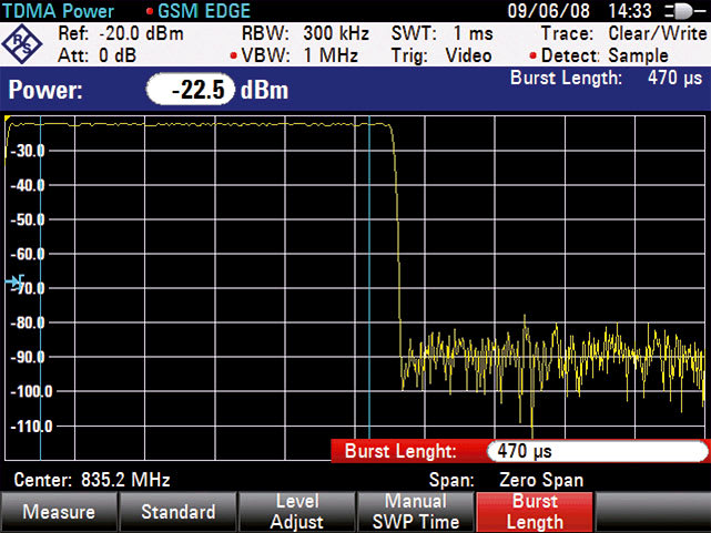
Power measurements on pulsed signals
The R&S FSH uses the TDMA power function to measure time-domain power within a time division multiple access (TDMA) timeslot. To make work easier for the user, all required instrument settings are already predefined for the GSM and EDGE standards.
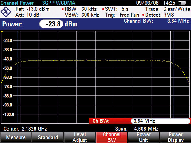
Channel power measurements
The R&S FSH uses the channel power measurement function to determine the power of a definable transmission channel. Channel power measurement for the LTE, WCDMA, GSM, TD-SCDMA, cdmaOne, CDMA2000 and 1xEV‑DO digital mobile communications standards is performed at a keystroke.
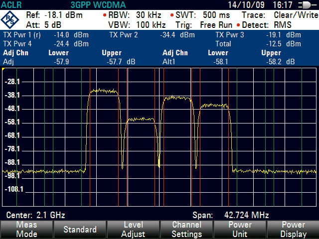
Adjacent channel power measurements
The ACLR measurement function enables the user to test how far a base station carrier signal reaches into the adjacent channel. An ACLR value that is too low indicates poor signal quality and can lead to interference on the adjacent useful signals.
The adjacent channel power can be displayed as an absolute value or relative to the useful carrier. The R&S FSH offers predefined settings for various transmission standards such as WCDMA, CDMA2000, 1xEV‑DO, TD-SCDMA and LTE, but parameters can also be user-defined. For example, users can enter different channel widths and spacings for up to 12 channels and up to 12 adjacent channels for the measurement of multicarrier signals.
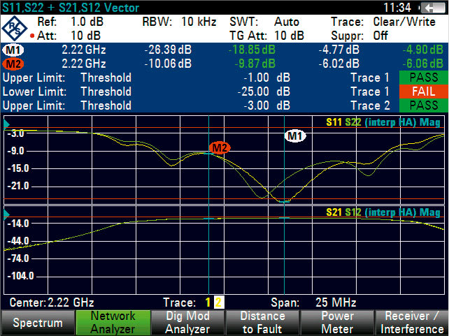
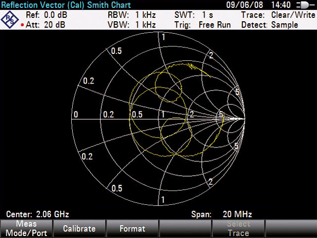
Vector network analysis
The vector measurements option adds a built-in tracking generator and an internal VSWR bridge, transforming the R&S®FSH models into a two-port vector network analyzer. Matching and transmission characteristics of filters, amplifiers, etc. can be determined quickly and with high accuracy in the forward and reverse direction with only one test setup. The built-in DC bias supplies power to active DUTs, such as amplifiers, via the RF cable. This function is especially useful for mast-mounted amplifiers in a base station.
- Higher measurement accuracy due to vector system error correction
- Measurement of magnitude and phase of S-parameters S112, S212, S12 and S22
- Simultaneous display of magnitude and phase in split-screen mode
- Simultaneous display of four different S-parameters
- Smith chart with zoom function
- Support of all conventional marker formats
- Input of a reference impedance for DUTs with an impedance other than 50 Ω
- Electrical length measurement
- Determination of group delay
- Measurement of matching characteristic of the antenna (return loss, reflection coefficient or VSWR)3
2 – Not applicable to R&S FSH13 and R&S FSH20
3 – Applicable only to R&S FSH models with built-in VSWR bridge (models .23/.24/.28/.30)
One-port cable loss measurements
The R&S FSH can determine the cable loss of installed cables without much effort. Simply connect one end of the cable to the R&S FSH measurement port. The other end of the cable is terminated with a short circuit or left open.

Distance-to-fault measurements
The distance-to-fault, caused by a pinched cable or by loose or corroded cable connections, is determined quickly and precisely. The built-in threshold function ensures that only true cable faults, i.e. faults that exceed a tolerance limit, are listed. This considerably simplifies measurement evaluation.
Directional power measurements up to 4 GHz
The R&S FSH-Z14 and R&S FSH-Z44 directional power sensors transform the R&S FSH into a full-featured directional power meter for the frequency ranges from 25 MHz to 1 GHz and from 200 MHz to 4 GHz. The R&S FSH can then simultaneously measure the output power and the matching of transmitter system antennas under operating conditions. The power sensors measure average power up to 120 W and normally eliminate the need for any extra attenuators. They are compatible with the common GSM/EDGE, 3GPP WCDMA, cdmaOne, CDMA2000 1x, DVB-T and DAB standards. In addition, the peak envelope power (PEP) up to max. 300 W can be determined.
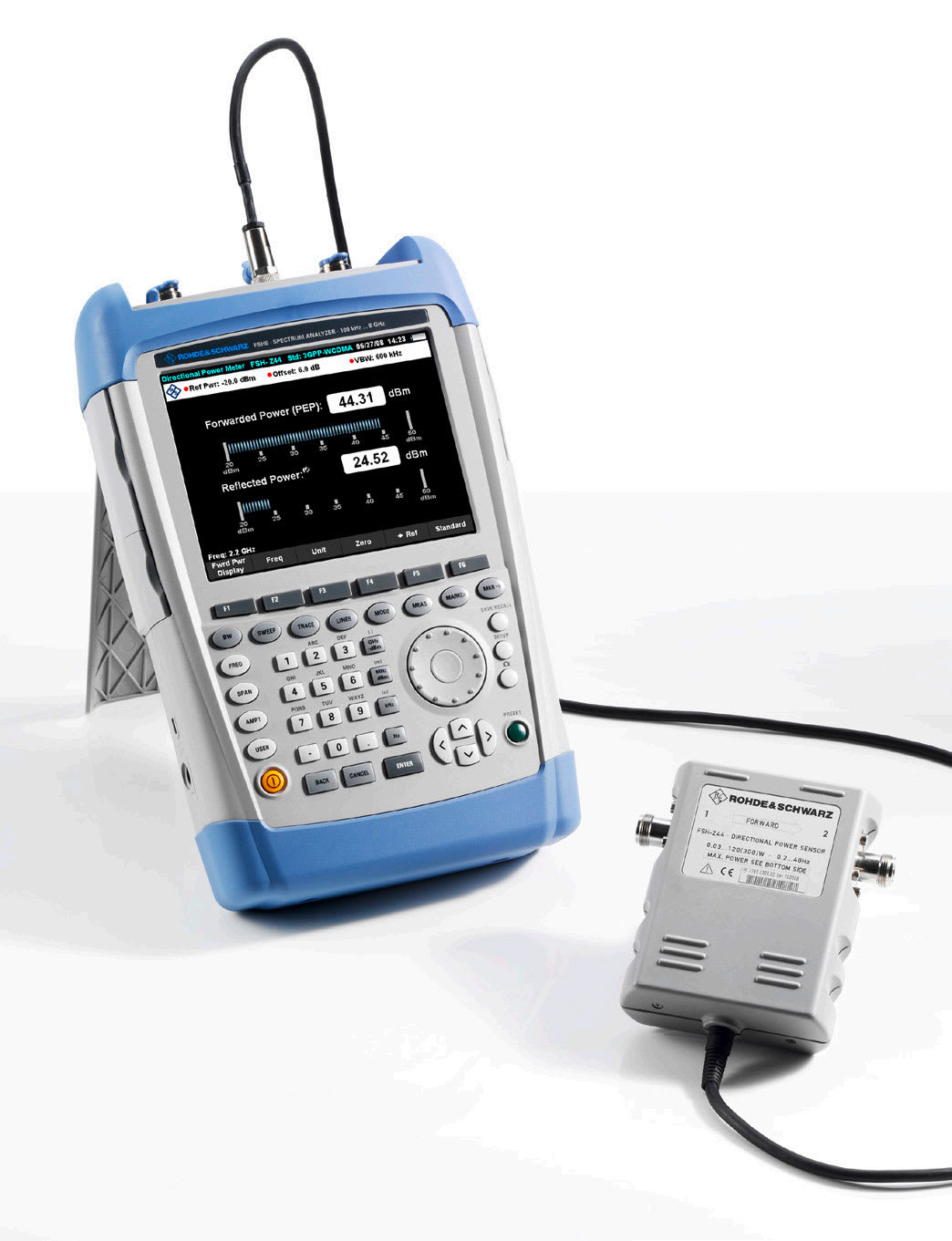
The R&S®FSH and the R&S®FSH-Z44 directional power sensor
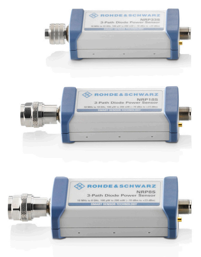
R&S®NRP power sensors
Highly accurate power measurements up to 110 GHz with terminating power sensors
Equipped with the R&S NRP USB power sensors, the R&S FSH becomes a highly accurate RF power meter up to 110 GHz with a dynamic range from -70 dBm to +45 dBm.
Measurement of Electromagnetic Fields
The R&S FSH can reliably determine the effects of electromagnetic fields (EMF) caused by transmitter systems.
Due to its large frequency range of up to 20 GHz, the R&S FSH covers all common wireless communications services, including GSM, CDMA, WCDMA, LTE, DECT, Bluetooth, WLAN (IEEE802.11a, b, g, n), WiMAX, broadcasting and television.
The R&S FSH is ideally suited for the following measurements:
- Determination of maximum field strength using directional antennas
- Direction-independent field strength measurements using an isotropic antenna
- Determination of electric field strength in a transmission channel with defined bandwidth (channel power measurement)
Field strength measurements with directional antennas
When measuring electric field strength, the R&S FSH takes into account the specific antenna factors of the connected antenna. The field strength is displayed directly in dBμV/m. If W/m2 is selected, the power flux density is calculated and displayed. In addition, frequency-dependent loss or gain, e.g. of a cable or amplifier, can be corrected. For simple result analysis, the R&S FSH provides two user-definable limit lines with automatic limit monitoring.
Field strength measurements with isotropic antennas
Equipped with the isotropic antennas of the R&S TS-EMF measurement system, the R&S FSH can determine the direction-independent resultant field strength in the frequency range from 9 kHz to 6 GHz. The antenna includes three orthogonally arranged antenna elements for measuring the resultant field strength. The R&S FSH sequentially activates the three antenna elements and calculates the resultant field strength, taking into account the antenna factors for each antenna element as well as the cable loss of the connection cable.
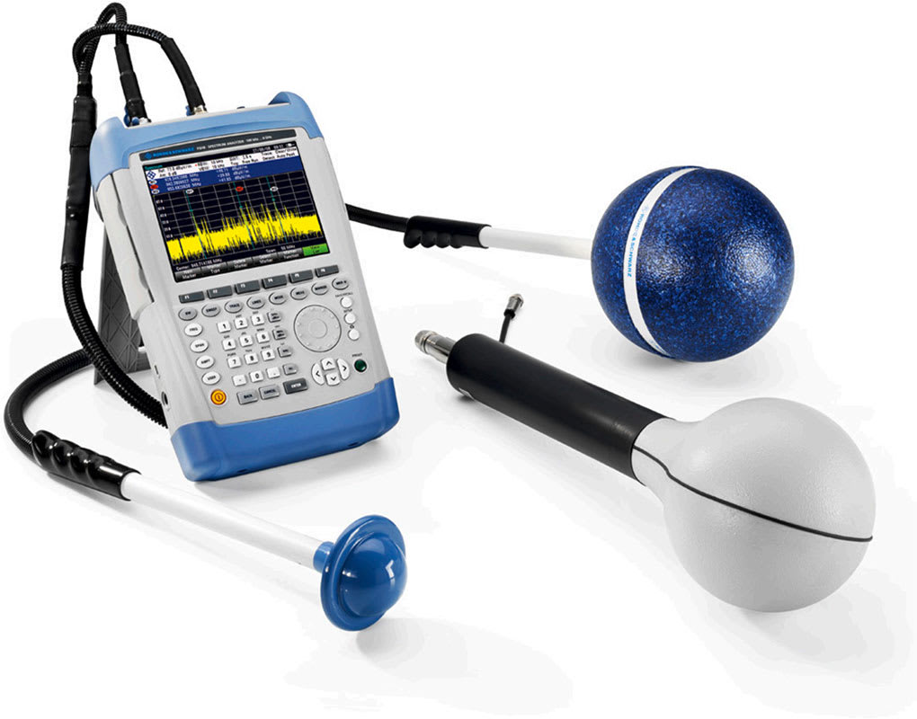
The R&S FSH with isotropic antennas

The R&S FSH with the R&S®HE400 antenna
EMF measurement application (R&S FSH-K105 option)
The R&S FSH-K105 option supports automated test sequences to perform frequency selective measurements.
The measurement is conveniently configured using the R&S Instrument View software. The configuration setup covers one or several sub-measurements on various frequencies or channels. It can include setting the limits of the EMF emissions in line with national and international standards during the configuration step or after the measurement. This provides a quick overview of whether the transmitter system complies with the applicable safety exposure limits. Pre-configuration is performed in the lab. This saves time and effort in the field. With just a few clicks, all test sequences are executed automatically. The result can be previewed on the analyzer or using the R&S Instrument View software where the results can be analyzed and documented.
| Overview of Handheld Analyzers | |||||||
| Applications | Customers | Measurements / functions required | Measurements/functions available in | ||||
| ZPH | ZVH | ZNH | FPH | FSH | |||
| Installation & maintenance | • Communication, mobile and broadcast operators and contractors • Satellite and radar system integrators, | Antenna performance | ✓ | K39 | ✓ | – | K42** |
| Cable performance | ✓ | K39 | ✓ | – | K42** | ||
| Cable fault identification | ✓ | ✓ | ✓ | – | K41** | ||
| Waveguide fault identification | – | K41 | – | – | ✓ | ||
| Filter performance | ✓* | K39 | ✓ | – | K41** | ||
| RF transmission / spectrum analysis | K1** | K1 | – | ✓ | ✓ | ||
| Power measurement with power sensor | K9 | ✓ | |||||
| AM/FM transmission [Radio broadcaster] | K7* | – | – | K7 | – | ||
| Pulse measurement [Radar customer] | K29 | ||||||
| EMF measurement (with TS-EMF antenna) | ✓*** | ✓*** | – | ✓*** | K105 | ||
| LTE demodulation measurement | – | – | – | – | K50/ K50E/ K51/ K51E | ||
| GPS information – Built-in GPS receiver External GPS receiver | B10* | – | |||||
| HA-Z240 (ZVH & FSH) / HA-Z340 (the rest) | |||||||
| Interference hunting | • Mobile and broadcast operators and contractors • Satellite and radar system You must be logged in to post a review. Manuals/GuidesBrochuresManualsSpec SheetsOther
Related productsSale 
Rohde and Schwarz FPL1003 – Signal and Spectrum Analyzer, 5 kHz to 3 GHzOriginal price was: $15,994.00.$12.10Current price is: $12.10. Add to cart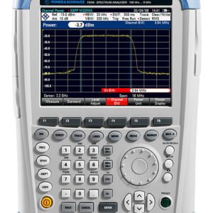 Rohde and Schwarz FSH13.23 ...
 $28,099.50
Our team of knowledgeable professionals is here to help you make informed decisions. Whether you need product recommendations, technical support, or guidance on your purchase, we're just a click away. Contact Us Now: 📧 sales@nestesinstruments.com 📞 +1 (833) 763-7837 Let us assist you in finding the perfect solution! | ||||||


Reviews
There are no reviews yet.