No products in the cart.

Description
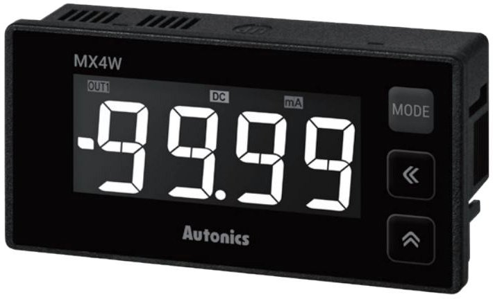
Autonics MX4W-A-FN LCD Display Multi Panel Meter

- 4-digit multimeter
- Size: DIN W96xH48mm
- Measurement input: DC/AC current
- Power supply: 24-240VAC 50/60Hz, 24-240VDC
- Output indicator
- Approx. 100g(approx. 77g)
The Autonics MX4W Series is 12-segment, LCD display multi-panel meter that features isolated input and power modules that allow the powering of multiple units using a single power supply. This multi-panel meter has a mounting space-saving and compact design with a size of DIN W96xH48 mm.
Analog to Digital Converter Method

(Figure 1) ACD basic configuration
The measuring speed is fast, and the resolution is high because of sampling the input signal on ADC and then measuring the changes by successive approximation ADC like figure 1. Successive approximation ADC which converts from the highest order bit toward the lower order bit has fast convert time and simple circuit.
Dual slope integration method

(Figure 2-1) Dual slope integration method basic configuration
Like (Figure 2-1) if SW1 is ON, input voltage Ex is integrated by a certain time Ts. After finish integral of input voltage Ex, SW2 is ON, then when connected to reference voltage Es, it will be integral in the direction of zero voltage. (Based on Es, Ex becomes reverse polarity.) When integral operating becomes zero, comparator stops integral, and this integral time is Tx.
The integral times of Successive approximation Es and input voltage Ex are fixed. So, if Tx value is measured with the counter, the digital value proportional to the input can be obtained.
Normal Mode Rejection Ratio (NMR)
NMR is the rate of ripple error caused by AC voltage when the AC voltage of commercial power frequency is mixed at the measuring input terminal during measuring DC voltage. To remove this error, the rate of removal is changed depending on the method of the A/D change.
At the integral method like (Figure 3), the half-cycle of + and the half cycle of – are canceling each other, so mixed noise can be removed effectively, and if the integral time of input is integral multiples of power frequency, it can get infinite noise to remove ratio theoretically. And if the filter method is inserted in the input circuit, NMR can be big, but it does not need to do because the response to reply to the change of signal voltage is worse.

(Figure 3)
Common Mode Rejection Ratio (CMR)
CMR is the rate of error that occurred when receiving noise voltage of the same phase (Common Mode) during the measuring input 2 terminals is the same size as in common(ground). The measured degree under the real operating condition can be declined often by the same phase noise. This noise is that when the potential difference at the earth terminal is caused between earth terminal of panel meter and the ground, the terrestrial current enters into the meter. It is represented between high and low measurement input terminal. The same phase noise can be neglected several V, dozens of V of the noise voltage when the earthing point is long, or the earthing points of a substation or the device using high power broadcasting is nearby. The definition of CMR is that using the circuit on the (Figure 4) when applied E (Common Mode Current: AC Peak voltage) if the output is changed as much as △E, the formula is below.

(Figure 4)
Temperature / PID Controllers | |
|---|---|
| Type (Controllers) | Digital |
| Size Rectangular | Other |
| # Digit Display | 4 |
| Display (Controllers) | LCD |
Panel Meters/Panel Meters Template | |
| Type (Panel Meter ) | Digital |
| Style (Panel Meter) | Rectangular/Square |
| Input (Panel Meters) | Current |
Product General Attributes | |
| Product Weight | 0.22 LBS |
You must be logged in to post a review.
Manuals/Guides
| Weight | 0.22 lbs |
|---|
Related products
Sale

Sale

Simpson 109ET Elapsed Time Meter Century, Round, Rectangular, and Wide-Vue Styles
Original price was: $97.99.$85.37Current price is: $85.37. Add to cartSale


 Autonics MX4W-A-FN LCD Display...
 $155.10
Our team of knowledgeable professionals is here to help you make informed decisions. Whether you need product recommendations, technical support, or guidance on your purchase, we're just a click away.
Contact Us Now:
📧 sales@nestesinstruments.com
📞 +1 (833) 763-7837
Let us assist you in finding the perfect solution!
Contact Us Now:
📧 sales@nestesinstruments.com
📞 +1 (833) 763-7837
Let us assist you in finding the perfect solution!
Reviews
There are no reviews yet.