No products in the cart.

Description
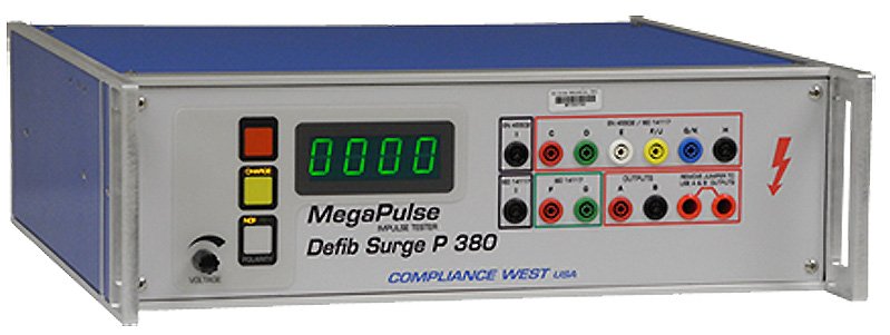
MegaPulse Surge Tester

Optional USB Testminder, computer control
Micro-controller technologies, front panel voltage meter indicates test peak open circuit voltage and polarity.
Built to the requirements of IEC 1180-1, Voltage Testers
Generates the waveforms described in EN60335, Paragraph 14 for testing electrical separation.
Compliance 380R Defibrillation Surge P Resistor Network for Defib Surge P 380
A Compliance West surge Tester. That means it outputs a guaranteed waveform but won’t bank. The tester outputs the waveform it is supposed to, time after time.
Built in the USA. Email and phone support free for life. Reasonable repair and calibration charges. Timely and helpful customer service always.
The Defib Surge P 380 outputs the pulse shown in and a Tw50 of 3 – 5.5ms when discharged protection, Fig. 110’s R7 and R1 are supplied internally. In accordance Megapulse Defib Surge P 380 can recharge and trigger the next pulse within 20 seconds.

Controls, Indicators, Connectors – MegaP ulse Defib Surge P 380 Front Panel
| ITEM | NAME | FUNCTION |
| 1 | VOLTAGE Adjust Knob | Adjust the voltage set point in the tester. Turn Clockwise to increase the output voltage after the CHARGE button has been pressed. Turn the knob fully counterclockwise (lowest voltage setting) before the start of each test, and afterthe end of each test. |
| 2 | POLARITY switch | Toggles the output pulse polarity from Normal to Reverse, Normal for positive and Reverse for Negative, The pulse will appear on the Output jack relative to the return jack The polarity switch only operates when the CHARGE indicator is lit and the voltage on the display meter is less than 180V. The polarity is Normal when the NOR indicator is lit and, Reverse when the REV indicator is lid. |
| 3 | NOR REV indicator | Indicates the state of the Output Polarity switch. NOR indicates Normal (Positive) position. REV indicates Reverse (Negative) position. |
| 4 | CHARGE switch | Starts the charge process of the tester capacitor. The CHARGE indicator will turn off after the CHARGE switch is pressed, and the TRIGGER indicator will turn on. The charge process will stop after 2 minutes if the TRIGGER button is not pressed. |
| 5 | CHARGE indicator | This Yellow indicator is lit to show that pressing the CHARGE switch is the next logical step in a test sequence. CHARGE indicator is lit when the tester is turn ON an after pressing TRIGGER button. CHARGE indicator will go out after pressing CHARGE button. CHARGE and TRIGGER Indicators will be blinking if the Interlock Switch is open. (Only testers with Interlock SwitchOption) |
| 6 | TRIGGER switch | Triggers the output impulse waveform. The impulse waveform will appear across the output leads. |
| 7 | TRIGGER indicator | This Red indicator is lit to show that the tester can be trigger. TRIGGER indicator is lit for 2 minutes after the CHARGE button is pressed. TRIGGER indicator will go out after pressing TRIGGER button. TRIGGER and CHARGE Indicators will be blinking if the Interlock Switch is open (Only testers with Interlock Switch Option) TRIGGER indicator will blink at when the Voltage. This effect will remain on until the TRIGGER switch is pressed. (Only testers with PC Interface option) |
| 8 | VOLTAGE meter | Displays the output voltage set point. The voltage reading will increase from zero to the voltage set point when the CHARGE button is pressed. Note that the Voltage meter may indicate that some residual voltage is present on the main storage capacitor, even when the tester is first turned ON. This is due to inherent charging of the internal capacitors. Pressing the TRIGGER switch will discharge the capacitors. Note that the peak amplitude of the measured output waveform is proportional to the voltage that is read of the front panel of the MegaPulse, but it will always be somewhat lower. This is because the meter on the MegaPulse is measuring the voltage on the main impulse storage capacitor. This voltage will intentionally dissipate to some extent before reaching the output leads. The meter will start to flash at 12210V to indicate that voltage is in the maximum limits. If unit includes PC Interface and the Keyboard is locked, the display will show OFF when a button is pressed. |
| 9 | OUTPUT jack | The impulse waveform appears on the OUTPUT jack, referenced to the RETURN jack. When the POLARITY switch is in the Normal position (NOR indicator is lit) the output will be a positive pulse. When the POLARITY switch is in the Reverse position (REV indicator is lit) the output will be a negative pulse. |
| 10 | RETURN jack | This is the return for the impulse waveform. This jack is referenced to the chassis of the MegaPulse, and is referenced to earth ground as long as the MegaPulse is properly grounded. Even though this jack is referenced to ground, it should be treated as hazardous whenever the MegaPulse is turned ON. |

Controls, Indicators, Connectors – MegaPulse Defib Surge P 380 Rear Panel
| ITEM | NAME | FUNCTION |
| 1 | Appliance Inlet /Fuseholder / Power Switch | Use supplied cordset to connect the MegaPulse 1.2×50-12P tester to an appropriate source of supply. Fuse holder provides access for Fuse replacement, and the Power Switch is used to turn the tester ON and OFF. |
| 2 | RS-232 Interface (Optional) | Apply a 5V (25mA) voltage signal for 500mS +/-200ms to start the Trigger process. |
| 3 | Interlock Switch (Optional) | Emergency Stop Close: Enables the tester buttons for operation. Open: Stops any process in the tester and disables the buttons. The TRIGGER and CHARGE Indicators will be blinking |
| 4 | Fuse replacement warning / Rating of power supply | Specifies replacement fuse and required supply voltage. |
Waveform Measurement Setup

Testing
This section describes how the MegaPulse Defib Surge P 380 tester is used to conduct a test. The test can be stopped immediately at any time by turning OFF the rear-panel power switch.
- Connect the tester to a proper source of supply using the included 18 AWG power supply cord.Make sure that the front panel VOLTAGE adjust knob is turned fully counterclockwise.
- Plug the Output and Return test leads into the jacks on the front panel.
- Connect the ends of the test leads to the equipment under test.
- Turn the Tester on. Toggle the POLARITY switch as needed so that the NOR or REV indicator is lit.
- Note that the Voltage meter may indicate that some residual voltage is present on the main storage capacitor, even when the tester is first turned ON. This is due to inherent charging of the internal capacitors. Pressing the TRIGGER switch will discharge the capacitors (be sure not to touch the output and return leads when pressing the trigger switch).
- Push the yellow CHARGE button. Verify the red TRIGGER indicator is now lit.
- Adjust the VOLTAGE knob so that the front panel LED display is reading a voltage that is suitable for the measuring instrument that is being used. Push the red TRIGGER button, when the desired voltage is displayed on the front panel meter.
- Note that the peak amplitude of the measured output waveform is proportional to the voltage that is read of the front panel of the MegaPulse, but it will always be somewhat lower. This is because the meter on the MegaPulse is measuring the voltage on the main impulse storage capacitor. This voltage will intentionally dissipate to some extent before reaching the output leads.
None
You must be logged in to post a review.
Manuals/Guides
Related products


 Compliance 380R Defibrillation...
Our team of knowledgeable professionals is here to help you make informed decisions. Whether you need product recommendations, technical support, or guidance on your purchase, we're just a click away.
Contact Us Now:
📧 sales@nestesinstruments.com
📞 +1 (833) 763-7837
Let us assist you in finding the perfect solution!
Contact Us Now:
📧 sales@nestesinstruments.com
📞 +1 (833) 763-7837
Let us assist you in finding the perfect solution!
Reviews
There are no reviews yet.