No products in the cart.


Description
Pico 9341-20 – 4 Channel, 20 GHz Sampling Oscilloscope

4 Channels
- 20 GHz Bandwidth, full
- Eye and mask testing to 16 Gb/s with up to 223-1 pattern lock
- Intuitive, touch-compatible Windows user interface
- Comprehensive built-in measurements, histogramming and editable data mask library
Designed for ease of use
The PicoSample 3 workspace takes full advantage of your available display size and resolution. You decide how much space to give to the trace display and the measurements display, and whether to open or hide the control menus. The user interface is fully touch- or mouse-operable, with grabbing and dragging of traces, cursors, regions and parameters. There are enlarged parameter controls for use on smaller touch displays. To zoom, either draw a zoom window or use the more traditional dual timebase, delay and scaling controls.
A choice of screen formats
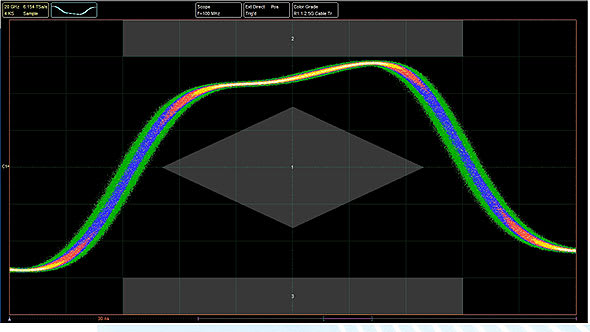
When working with multiple traces, you can display them all on one grid or separate them into two or four grids. You can also plot signals in XY mode with or without additional voltage-time grids. The persistence display modes use color-coding or shading to show statistical variations in the signal. Trace display can be in either dots-only or vector format.

Up to 25 GHz electrical bandwidth
The PicoScope 9300 series offers models at 15, 20 and 25 GHz with low sampling jitter and fine timing resolution to support measurement of transitions down to 14 ps (calculated). Among the fastest of all sampling oscilloscopes, the 9300 Series captures your waveform at up to 1 MS/s with timing resolution down to 64 fs and with 16-bit vertical resolution. It achieves lively trace, persistence and eye updates, greater than 60 dB dynamic range, and trace lengths up to 32 kS.

Trigger modes
2.5 GHz direct and up to 15 GHz prescaled trigger: Sampling oscilloscopes accept their trigger from a separate input, either directly for repetition rates up to 2.5 GHz or via a prescaling divider input, for repetition rates up to 15 GHz (14 GHz on 15 and 20 GHz models).
Built-in 11.3 Gb/s clock data recovery trigger: To support serial data applications in which the data clock is not available as a trigger, or for which trigger jitter needs to be reduced, the PicoScope 9302 and 9321 include a clock recovery module. This continuously regenerates the data clock from the incoming serial data or trigger signal and can do so with reduced jitter even over very long trigger delays or for pattern lock applications. A divider accessory kit is included to route the signal to both the clock recovery and oscilloscope inputs.

Eye-diagram analysis
The PicoScope 9300 Series scopes quickly measure more than 30 fundamental parameters used to characterize non-return-to-zero (NRZ) signals and return-to-zero (RZ) signals. Up to ten parameters can be measured simultaneously, with comprehensive statistics also shown.

The measurement points and levels used to generate each parameter can optionally be drawn on the trace. Eye-diagram analysis can be made even more powerful with the addition of mask testing, as described later in this data sheet.
Pattern sync trigger and eye line mode
When a repeating data pattern such as a pseudorandom bit sequence is present, an internal trigger divider can lock to it. You can then use eye-line mode to move the trigger point, and view point, along the whole pattern, bit by bit.
Eye-line scan mode is also available to build an eye diagram from a user-selected range of bit intervals through to the whole pattern. These features are useful for analyzing data-dependent waveshapes.
Mask testing
PicoSample 3 has a built-in library of over 160 masks for testing data eyes. It can count or capture mask hits or route them to an alarm or acquisition control. You can stress test against a mask using a specified margin, and locally compile or edit masks.
There’s a choice of gray-scale and color-graded display modes to aid in analyzing noise and jitter in eye diagrams. There is also a statistical display showing a failure count for both the original mask and the margin. The extensive menu of built-in test waveforms is invaluable for checking your mask test setup before using it on live signals.

Mask test features
- Failure count
- User-defined margins
- Count fails
- Built-in standard test waveforms
- Stop on fail
9.5 GHz optical model
The PicoScope 9321-20 includes a built-in precision optical-to-electrical converter. With the converter output routed to one of the scope inputs (optionally through an SMA pulse shaping filter), the PicoScope 9321-20 can analyze standard optical communications signals such as OC48/STM16, 4.250 Gb/s Fibre Channel and 2xGB Ethernet. The scope can perform eye- diagram measurements with automatic measurement of optical parameters including extinction ratio, S/N ratio, eye height and eye width. With its integrated clock recovery module, the scope is usable to 11.3 Gb/s.
The converter input accepts both single-mode (SM) and multi-mode (MM) fibers and has a wavelength range of 750 to 1650 nm.

TDR/TDT analysis
The PicoScope 9311 oscilloscopes feature built-in step generators for time-domain reflectometry and transmission measurements. The 9311-15 integrates a single rising step generator suited to single-ended TDR/TDT applications, while the 9311-20 features deskewable rising and falling step generators suited to single-ended and differential measurements. These features can be used to characterize transmission lines, printed circuit traces, connectors and cables with 16 mm resolution for impedance measurements and 4 mm resolution for fault detection.
 Connection diagrams: PicoScope 9311 sampling oscilloscopes in use with devices under test (DUT) in TDR and TDT applications
The PicoScope 9311-15 and 9311-20 generate 2.5 to 7 V steps with 60 ps rise time from built-in step recovery diodes. They are supplied with a comprehensive set of calibrated accessories to support your TDR/TDT measurements, including cables, signal dividers, adaptors, attenuator and reference load and short.
The PicoScope 9311-20 TDR/TDT model includes source deskew with 1 ps resolution and comprehensive calibration, reference plane and measurement functions. Voltage, impedance or reflection coefficient (ρ) can be plotted against time or distance.
An alternative approach to TDR/TDT capability is to pair any 9300 Series scope with a standalone PG900 pulse generator. These instruments include similar differential step recovery diode step generators and also offer an option of 40 ps tunnel diode step generation. This brings extra flexibility and the ability to remotely position the pulse source. The generators also enable TDT and TDR with the PicoScope 9301, 9302 clock recovery, 9321 optical and 9341 4-channel sampling oscilloscopes.
Measurement of over 100 waveform parameters with and without statistics
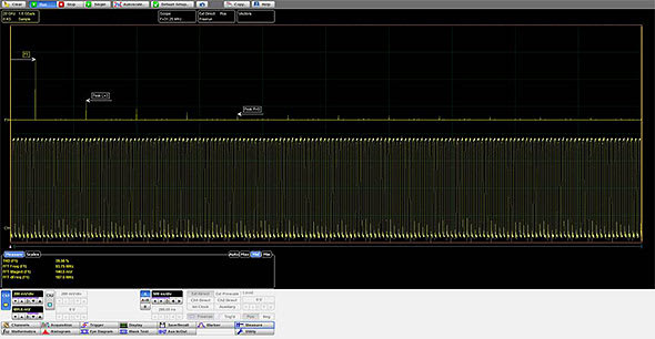
The PicoScope 9300 Series scopes quickly measure well over 100 standard waveform and eye parameters, either for the whole waveform or constrained between markers. The markers can also make on-screen ruler measurements, so you don’t need to count graticules or estimate the waveform’s position. Up to ten simultaneous measurements are possible. The measurements conform to IEEE standard definitions, but you can edit them for non-standard thresholds and reference levels using the advanced menu or by dragging the on-screen thresholds and levels. You can apply limit tests to up to four measured parameters.
A dedicated frequency counter shows signal frequency at all times, regardless of measurement and timebase settings.

Powerful mathematical analysis
The PicoScope 9300 Series scopes support up to four simultaneous mathematical combinations or functional transformations of acquired waveforms.
You can select any of the mathematical functions to operate on either one or two sources. All functions can operate on live waveforms, waveform memories or even other functions. There is also a comprehensive equation editor for creating custom functions of any combination of source waveforms.
FFT analysis
All PicoScope 9300 Series oscilloscopes can calculate real, imaginary and complex Fast Fourier Transforms of input signals using a range of windowing functions. The results can be further processed using the math functions. FFTs are useful for finding crosstalk and distortion problems, adjusting filter circuits designed to filter out certain harmonics in a waveform, testing impulse responses of systems, and identifying and locating noise and interference sources.
Histogram analysis
Behind the powerful measurement and display capabilities of the 9300 Series lies a fast, efficient data histogramming capability. A powerful visualization and analysis tool in its own right, the histogram is a probability graph that shows the distribution of acquired data from a source within a user-definable window.


Histograms can be constructed on waveforms on either the vertical or horizontal axes. The most common use for a vertical histogram is measuring and characterizing noise and pulse parameters. A horizontal histogram is typically used to measure and characterize jitter.
Compact, portable USB instruments
These units occupy very little space on your workbench and are small enough to carry with your laptop for on-site testing, but that’s not all. Instead of using remote probe heads attached to a large bench-top unit, you can now position the scope right next to the device under test. Now all that lies between your scope and the DUT is a short, low- loss coaxial cable. Everything you need is built into the oscilloscope, with no expensive hardware or software add-ons to worry about.


Software Development Kit
The PicoSample 3 software can operate as a stand-alone oscilloscope program or under ActiveX remote control. The ActiveX control conforms to the Windows COM interface standard so that you can embed it in your own software. Unlike more complex driver-based programming methods, ActiveX commands are text strings that are easy to create in any programming environment.
Programming examples are provided in Visual Basic (VB.NET), MATLAB, LabVIEW and Delphi, but you can use any programming language or standard that supports the COM interface, including JavaScript and C. National Instruments LabVIEW drivers are also available. All the functions of the PicoScope 9300 and the PicoSample software are accessible remotely.
PicoConnect 900 Series: the shape of probes to come (Optional)
The PicoConnect 900 Series is a range of low-invasive, high-frequency passive probes, designed for microwave and gigabit applications up to 9 GHz and 18 Gb/s. They deliver unprecedented performance and flexibility at a low price and are an obvious choice to use alongside the PicoScope 9300 Series scopes.
Features of the PicoConnect 900 Series probes
- Extremely low loading capacitance of < 0.3 pF typical, 0.4 pF upper test limit for all models
- Slim, fingertip design for accurate and steady probing or solder-in at fine scale
- Interchangeable SMA probe heads at division ratios of 5:1, 10:1 and 20:1, AC or DC coupled
- Accurate probing of high speed transmission lines for Z0 = 0 Ω to 100 Ω
- Specified probe ratio compensated to correct for loading of the low-impedance probe input
- Class-leading uncorrected pulse/eye response and pulse/eye disturbance
- High dynamic range, low noise, and implicit linearity and long-term flatness of a passive design
- Tolerant of very high input slew rate, hardened to EM discharge and no saturation and recovery characteristic. Can address high-amplitude pulse and burst applications.
- Screened to minimize noise or response change caused by finger proximity or EM interference
- Supplied with robust, high-performance, highly flexible low-loss microwave coaxial cable
 Ultra-compact: the probe head is just 68 mm long and weighs only 5 g
PicoSource PG900 Series differential pulse generators (Optional)
Built-in signal generator
All the PicoScope 9300 Series scopes can generate industry-standard and custom signals including clock, pulse and pseudo-random binary sequence. You can use these to test the instrument’s inputs, experiment with its features and verify complex setups such as mask tests. AUX OUTPUT can also be configured as a trigger output.

For greater versatility than a built-in signal generator can offer, you may want to separate your high-performance fast-step TDR/TDT pulse source from the sampling oscilloscope and have two instruments to use either stand-alone or together as required. The PicoSource PG900 Series generators contain the same step recovery diode pulse source as the PicoScope 9311, or slightly faster but reduced amplitude tunnel diode pulse heads, rehoused in a separate USB-controlled instrument. All are supplied with PicoSource PG900 control software.
Choose from three models
- PicoSource PG911 with integrated 60 ps pulse outputs
- PicoSource PG912 with 40 ps pulse tunnel diode heads
- PicoSource PG914 with both types of output
 Intuitive Windows-based software
Key specifications
PicoSource PG911 and PG914
- Integrated 50 Ω SMA(f) step recovery diode outputs
- < 60 ps single-ended pulse transition time
- Two 2.5 V to 7 V variable amplitude outputs
- ±1 ns timing deskew in 1 ps steps
- 20 dB 10 GHz SMA(m-f) attenuators supplied fitted to SRD pulse outputs
PicoSource PG912 and PG914
- External 50 Ω N(m) positive and negative tunnel diode pulse heads
- < 40 ps pulse transition time
- Fixed 200 mV output amplitude
- ±500 ps timing deskew in 1 ps steps
- Inter-series N(f)–SMA(m) adaptors included with pulse heads
All PicoSource PG900 models
- Differential outputs
- 200 ns to 4 μs pulse width
- Adjustable 1 μs to 1 s internal clock period
- Typical 3.0 ps RMS jitter relative to external trigger
SMA Bessel-Thomson pulse-shaping filters (Optional)
For use with the 9321-20 optical to electrical converter, a range of Bessel–Thomson filters is available for standard bit rates. These filters are essential for accurate characterization of signals emerging from an optical transmission system.
 O/E converter output, raw
Above is the ringing typical of an unequalized O/E converter output at 622 Mb/s.
 O/E converter output, filtered
Above is the result of connecting the 622 Mb/s B-T filter. This is an accurate representation of the signal that an equalized optical receiver would see, enabling the PicoScope 9321-20 to display correct measurements.
PicoScope 9300 Series inputs and outputs


| PicoScope | 9301-15 | 9301-25 | 9302-15 | 9302-25 | 9311-15 | 9311-20 | 9321-20 | 9341-20 | 9341-25 |
| 15 GHz sampling oscilloscope | ✔ | ✔ | ✔ | ||||||
| 20 GHz sampling oscilloscope | ✔ | ✔ | ✔ | ||||||
| 25 GHz sampling oscilloscope | ✔ | ✔ | ✔ | ||||||
| 2 channels | ✔ | ✔ | ✔ | ✔ | ✔ | ✔ | ✔ | ||
| 4 channels | ✔ | ✔ | |||||||
| Clock recovery (11.3 Gb/s) | ✔ | ✔ | ✔ | ||||||
| Optical input (9.5 GHz) | ✔ | ||||||||
| Integrated TDR/TDT (60 ps / 2.5 to 7 V) | ✔ | ✔ |
Oscilloscopes/Digital Oscilloscopes Template | |
|---|---|
| Bandwidth | 20 GHz (20000 MHz) |
| Channels | 4 |
| Sampling Rate | 1 MS/S (0.001 GS/S) |
| Rise Time | 17.5 ps (0.018 ns) |
Oscilloscopes/PC Based Oscilloscopes Template | |
| Bits | 16 |
| Power | AC |
Product General Attributes | |
| Unique Features | 4 Channel 20 GHz Sampling Oscilloscope |
| Warranty | 2 YEARS |
| Warranty Details | 2 years warranty (1 year for input sampler) |
| Safety Approval | CE |
| Interfaces I/O | LAN / Ethernet, USB |
| Product Weight | 2.86 LBS |
| Product Height | 1.57 IN |
| Product Length | 10.23 IN |
| Product Width | 6.69 IN |
| Shipping Weight | 7.00 LBS |
| HTS/Schedule B Number | 90302000 |
| Calibration Included | Factory Calibration |
| Country of Origin | Lithuania |
You must be logged in to post a review.
| Weight | 2.86 lbs |
|---|---|
| Dimensions | 10.23 × 6.69 × 1.57 in |
Related products


 Pico 9341-20 4 Channel, 20 GHz...
 $33,599.50
Our team of knowledgeable professionals is here to help you make informed decisions. Whether you need product recommendations, technical support, or guidance on your purchase, we're just a click away.
Contact Us Now:
📧 sales@nestesinstruments.com
📞 +1 (833) 763-7837
Let us assist you in finding the perfect solution!
Contact Us Now:
📧 sales@nestesinstruments.com
📞 +1 (833) 763-7837
Let us assist you in finding the perfect solution!
Reviews
There are no reviews yet.