No products in the cart.

Description
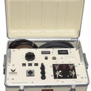
SMC PTE-100-V – Single Phase Relay Test Set, Voltage/Current, 300V/8A

- Variable voltage to 300 V or current to 8 A
- Variable frequency from 40 to 420 Hz
- Variable phase angle between 0 – 3599°
- Output power: 100 VA
- Reversible output voltage/current
- Outputs are fully isolated and electronic
- Dynamic capability
- Completely programmable
- External current or voltage reference input
- External timer control output
Electronic PTE Test Equipment Range
The electronic PTE test equipment range has been designed for maximum efficiency and simplicity when testing protective relays in the field. These universal, rugged and powerful units provide the required accuracy and performance to test any electromechanical, static, or numerical relay. Output waveforms are digitally synthesized, and completely isolated from the mains supply. The signal is then electronically amplified to attain up to 50 A or 300 V with an effective power of 100 VA.
Flexibility
The range includes four products: the PTE-300-V, with three output channels, and the smaller PTE- 100-V, with one channel only, are mainly designed for voltage-related protections like generator, motor and synchronizing relays. The other two (PTE-50-CET and the one-channel version PTE-50-CE) are specially powerful in current-based testing.
Each output channel in these units can be switched between current and voltage injection by just pressing a button. Amplitude and phase angle can also be adjusted independently in each channel. One of the biggest advantages in the PTE sets is their ability to communicate to each other, in order to use all their output channels simultaneously. You can purchase several simple units for the most frequent testing and, when time arrives for more demanding tasks, interconnect two or three according to the application’s requirements. This is a cost-effective solution when you need more than one test set.
Furthermore, the PTE units can also be used in combination with equipment from other manufacturers, thanks to their built-in external synchronization input.
Need computer-generated reports? Not only does the PTE range feature the best manual control board in the market, but also the possibility to operate automatically under the control of optional software from a standard computer. This capability is especially useful when a great number of different protections must be tested periodically. Relay types and test routines are stored in a custom-defined database, so that you only need to double-click on each installed relay’s entry to perform the complete test process and to save and produce a report in a fully unattended manner. The automatic testing software can also control combinations of several PTE units as if it was a single device.
Power
Behind the 100-VA output power in the PTE channels, you will find a generous duty cycle and a great number of test resources. For example, several channels can be controlled from a single button, even if they belong to various interconnected units, thanks to the master/slave function. And you can refer the phase angle of each channel or the base frequency of the harmonics function to an incoming signal from an external generator, or setup ROCOF frequency ramps in less than one minute without a computer.
The PTEs feature an idle power mode to save energy and keep the amplifiers cool when testing low impedance relays. Each output channel provides an independent neutral, which enables the interconnection of two or more channels in series or in parallel with absolute freedom. The optional PTE-SER plug allows the injection of up to 50A with a compliance voltage of up to 60V in the PTE-50-CET.
Output Characteristics
| PTE-50-CE | PTE-50-CE Pro | PTE-50-CET | PTE-100-V | PTE-300-V | |
| Output channels | 1 | 2 | 3 | 1 | 3 |
| Current per channel | 0-50 A | 3 x 0-50 A | 0-8 A | 3 x 0-8 A | |
| Voltage per channel | 0-150 V | 0-150 V, 0-140 V | 3 x 0-150V | 0-300 V | 3 x 0-300 V |
| Chronometer | Yes | No | |||
Assisted Manual Control
The comprehensive and well-designed control board in the PTE units provides fast and accurate operation for the simplest one-shot testing to the most complex dynamic fault simulation. The board’s design and the studied position of each control and button is uniform and coherent, so that all the units are operated in the same way. The three-channel versions feature a master/slave function that allows to control and adjust two or three channels simultaneously from channel #1. You just adjust the pre-fault and fault quantities, launch the simulation and note the reading from the chronometer.
Dynamic Simulation
Each channel can store two sets of amplitude (voltage or current) and phase angle parameters in memory. You can then step into fault state from zero or from non-fault values. You can also edit and playback digitized transients in COMTRADE format from an external PC using optional software.
Control BUS
The EuroSMC’s exclusive PTE BUS, supplied as standard equipment, allows the interconnection of up to five PTE units in order to use all their output channels simultaneously. Phase and frequency synchronization signals, as well as output control messages, timer start/stop commands and trip signal detection messages, are transmitted by this high-speed bus in real time. Any unit can be set as master or slave in the system’s operational hierarchy. The PTE BUS integrates the resources of each individual unit into a single virtual system that can be operated from the master unit or from an external computer.
Digital Instrumentation
All the instruments are digital, including the chronometer, the frequency generator and the injection measurement displays. Quantities are adjusted with contact-free digital encoders on high-contrast LED indicators. The adjustment speed and resolution is easily controlled by selecting the digit to be modified. The chronometer features six start/stop modes selectable by pressing a button, and can be set to display milliseconds or cycles of the working frequency. The frequency generation module features a fully programmable ramp for ROCOF testing and a direct adjustment method with two modes: absolute frequency and delta (incremental) mode referred to an external signal’s frequency.

Digital Timer

Harmonic Selector
Software Applications
Roots
ROOTS (Relay Object-Oriented Test Software) provides the best solution to the testing of today’s multifunctional IEDs by performing accurate fault calculation, sequential test execution, and reporting automatically.
ROOTS is an optional product for computer-based operation of EuroSMC relay test sets. ROOTS is developed using the latest Microsoft.NET® technology and is available for 32-bit and 64-bit Windows XP, Vista and Windows 7 platforms. ROOTS storage files are self-contained databases where relay data, characteristics, custom formulas, test routines and report definitions are saved according to a simple hierarchy that is flexible and easy to understand, with a modular architecture. Relays can be defined as templates by using equations instead of fixed values for the device’s characteristics and definitions. Relay characteristics can be defined in ROOTS from scratch or imported from RIO files. Test procedures defined within ROOTS can be directly executed on a connected EuroSMC test set.
For every functional module of the device under test – Distance, Overcurrent, Differential module, RIO, etc – multiple tests can be attached from a wide choice of test types (click sequence, search, reclose, CB failure, SOTF, fuse fail, etc) including scheme-oriented tests.
ROOTS features a powerful interactive graphical editor for geometrical definitions of protective characteristics and zones. Lines and curves can be drawn in free hand mode, imported from a templates library and / or adjusted using numerical values and coordinates.
ROOTS implements a friendly, easy to use interface, for the quick and accurate configuration of all equipment features, device settings, test modules, test results and reports. The test report can be easily customized and exported according to user needs.
ROOTS users are covered by EuroSMC’s lifetime update warranty, which provides free, unlimited access to new releases and software modules of ROOTS.


EuroFAULT
If you have oscillographic recordings of faults and transients in digital COMTRADE format, you can play them back into your relay with EuroFAULT. You only need to open the file from the program, assign the voltage and current components to the available channels in your PTE unit or combination and click on PLAYBACK.


PTE-COM
PTE-COM is the command language used by software applications to control the PTE equipment from a computer. The PTE-COM commands, interpreted by the PTE-12 interface during the software-controlled test process, are available to the users for the development of their own custom applications and test automation procedures, if needed.
None
You must be logged in to post a review.
Manuals/Guides
Related products


Sale

TPI 753a Refrigerant Leak Detector
Original price was: $219.94.$202.34Current price is: $202.34. Add to cartSale
CPS LS790B – Leak Seeker Refrigerant Leak Detector
Original price was: $344.47.$298.53Current price is: $298.53. Add to cart SMC PTE-100-V Test Set Voltage...
 $12,402.50
Our team of knowledgeable professionals is here to help you make informed decisions. Whether you need product recommendations, technical support, or guidance on your purchase, we're just a click away.
Contact Us Now:
📧 sales@nestesinstruments.com
📞 +1 (833) 763-7837
Let us assist you in finding the perfect solution!
Contact Us Now:
📧 sales@nestesinstruments.com
📞 +1 (833) 763-7837
Let us assist you in finding the perfect solution!
Reviews
There are no reviews yet.